 in the direction of
the rotation axis, and the angle of rotation,
in the direction of
the rotation axis, and the angle of rotation,
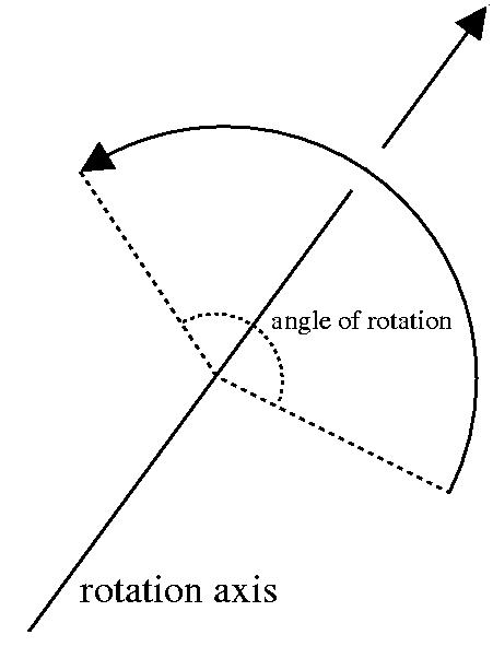
Euler's theorem states that any rotation of an object in 3D space leaves some axis fixed, the rotation axis.
As a result, any rotation can be described by a vector
in the direction of
the rotation axis, and the angle of rotation,
![]() , about
, about ![]() . The direction of
rotation is chosen
so that as you look in the direction of
. The direction of
rotation is chosen
so that as you look in the direction of ![]() ,
the rotation
is counterclockwise about the origin for
,
the rotation
is counterclockwise about the origin for ![]() .
The following
figure illustrates a rotation and its rotation axis.
.
The following
figure illustrates a rotation and its rotation axis.
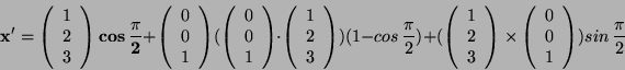
We can use the following rotation formula for rotating a point ![]() by an angle
by an angle ![]() , about a vector
, about a vector ![]() to reach
to reach ![]() .
.
This formula has a simple geometric derivation, which can be found at: http://mathworld.wolfram.com/RotationFormula.html
However the above formula can also be expressed in terms of matrices.
The corresponding rotation matrix, can be obtained in terms of ![]() and
the components of
and
the components of ![]() , giving a total of 4 parameters.
, giving a total of 4 parameters.
The axis-angle form is usually written as a 4-vector: [![]() ].
].
To describe continuous rotation in time, you treat n and ![]() as
functions of time.
as
functions of time.
A simple example
Using the above formula we shall rotate the point
 by angle
![]() , around the rotation axis
, around the rotation axis
 , to obtain the new
point
, to obtain the new
point ![]() .
.
Substituting these values in we have:
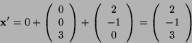
This figure is correct as ![]() was rotated around
the
z-axis by
was rotated around
the
z-axis by ![]() , so the z co-ordinate remains constant,
whilst the new x and y co-ordinates are now perpendicular from the
old co-ordinates, as demonstrated by the dot product:
, so the z co-ordinate remains constant,
whilst the new x and y co-ordinates are now perpendicular from the
old co-ordinates, as demonstrated by the dot product:
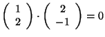 .
.
Disadvantages of this representation
There are three sources of redundancy with the axis-angle rotation
specification. Let R(![]() ,
,![]() )
represent a rotation
about the axis
)
represent a rotation
about the axis ![]() , by angle
, by angle ![]() .
.
 . This reduces the
degrees of freedom of our parameters to 3, as
once
. This reduces the
degrees of freedom of our parameters to 3, as
once