Epipolar geometries are commonly used in the computer vision community for recovery of depth by stereo reconstruction, (Trucco and Verri [5]). The basis for the epipolar geometry is the plane containing two camera optical centers and the workspace point of interest. The epipolar relation then allows for associating the workspace point projection in the first image to a corresponding line in the second image. The existence of this invariant reduces the search for corresponding points from 2D to a 1D problem.
In (Livatino [1]) correspondences must occur along cylindrical epipolar lines. The cylindrical epipolar line represents a geometric constraint for cylindrical projections that determines the possible positions of a point given its position in some other cylinder. This constraint plays the same role that the epipolar geometry plays for planar projections, [4].
In particular, every point in the considered cylinder corresponds to a ray in space as given by the cylindrical epipolar relation represented in equation 1. When one of the rays is observed from another cylinder, its path projects to a curve which appears to begin at the point corresponding to the origin of the considered cylinder, and it is constrained to pass through the points image on the other cylinder.
Cylindrical projection, however, do not preserve lines.
In general, lines map to quadratic parametric curves on the surface of
a cylinder.
The paths of these curves are uniquely determined sinusoids.
The equation 1 gives a concise expression for the curve,
![]() , formed by the
projection of a ray across the surface of a cylinder, (labeled
"right"), where the ray is specified by its positions on some other
cylinder, (labeled "left").
The cylindrical epipolar curve can be completely specified with no more
information that it was needed for the planar case.
The geometry of cylindrical epipolar lines is illustrated by the
example in figure 1, and it can be computed
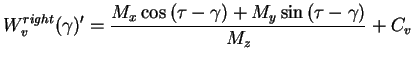
as in [4] using the following equation:
, formed by the
projection of a ray across the surface of a cylinder, (labeled
"right"), where the ray is specified by its positions on some other
cylinder, (labeled "left").
The cylindrical epipolar curve can be completely specified with no more
information that it was needed for the planar case.
The geometry of cylindrical epipolar lines is illustrated by the
example in figure 1, and it can be computed
as in [4] using the following equation:
where
![\begin{displaymath}\left[
\begin{array}{c}
M_x \\
M_y \\
M_z
\end{array}\right...
...- W^{left}_{\gamma})} \\
C_v - W^{left}_{v}
\end{array}\right]\end{displaymath}](img3.png) |
(2) |
![]() represents the angle
represents the angle
![]() and the ordinate
and the ordinate ![]() of landmark-center location in the
left-panorama image-plane,
of landmark-center location in the
left-panorama image-plane,
![]() represents
the correspondent ordinate
represents
the correspondent ordinate ![]() for a certain angle
for a certain angle ![]() , in the
right panorama,
, in the
right panorama,
![]() is the rotation offset which aligns the angular orientation of
the cylinders to a common frame,
and
is the rotation offset which aligns the angular orientation of
the cylinders to a common frame,
and ![]() is the ordinate
is the ordinate ![]() of the scan-line where the center of the
projection would project onto the scene, (i.e. the ordinate of the
line of zero elevation).
of the scan-line where the center of the
projection would project onto the scene, (i.e. the ordinate of the
line of zero elevation).
![]() and
and
![]() represent respectively the left and the right camera positions.
represent respectively the left and the right camera positions.
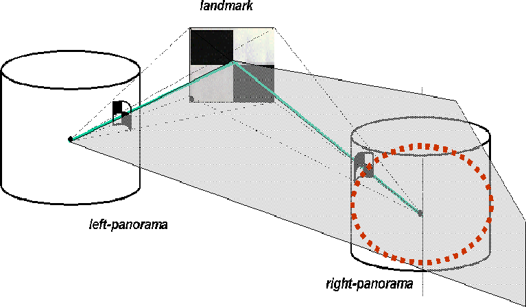 |
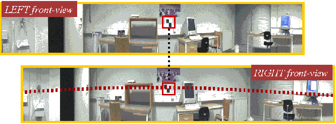
Figure 2 bottom-row shows the cylindrical epipolar line, (the dot-line), superimposed to its related panoramic view. The cylindrical epipolar line is related to the "ideal" landmark, [1].
 |
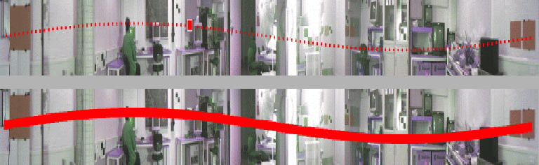
Searching along epipolar lines makes the stereo correspondence computation faster since the search only takes place in a prescribed area along the line. Figure 3 bottom-row shows an example of search area, (the thick red line), for the epipolar line represented in figure 3 top-row. The surface-width of a search area depends on the expected error in landmark location in the camera image-plane, (and other things).
 |
Let the visual template size be ![]() x
x ![]() and the size of the
search-window,
and the size of the
search-window, ![]() x
x ![]() .
The size of the search-window is set in [1] to
.
The size of the search-window is set in [1] to
![]() and
and
![]() .
As for the incremental step, that is, the distance between two
consecutive search windows along the epipolar line, this is set to
.
As for the incremental step, that is, the distance between two
consecutive search windows along the epipolar line, this is set to
![]() .
The proposed incremental step,
.
The proposed incremental step, ![]() , has been chosen
in order to set the precise pixel-distance which
would allow two consecutive search windows to identify twice any landmark
template lying in-between the two search windows.
, has been chosen
in order to set the precise pixel-distance which
would allow two consecutive search windows to identify twice any landmark
template lying in-between the two search windows.
Such an incremental step might be seen as a waste of computational time because each valid matched area is probably going to be checked twice (into two consecutive search windows). However, the proposed technique has shown to be very useful in order to reject unsuitable landmark templates as well as confirm valid matches. In particular, a match which is found twice in the same position in two consecutive search windows (along an epipolar line), is very likely a valid match. This was experienced for most of the successful matches, [1]. On the contrary, any match which is not confirmed by a consecutive match despite it could be, is discarded since in this case it is possible that the result will be an ambiguous texture patch.
Other than allowing for a faster computation, searching along epipolar lines makes the correspondence problem much more reliable since it prevents from false matches which could have been found outside the prescribed searching area. In addition, based on the geometry of the stereo situation, it is sufficient to only search along a portion of epipolar line which should corresponds to the regions of workspace which are potentially most suitable to landmarks.
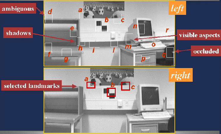
Experiments demonstrated that searching along epipolar lines allowed for identification and rejection of ambiguous and poorly textured landmarks. This was achieved by using normalized cross-correlation and checking for multiple matches along the epipolar-lines. Figure 4 represents an example where unsuitable landmarks were successfully discarded. The figure top-row shows the landmarks extracted by running the attention selection mechanism proposed in (Livatino [1], [2], [3]) and the figure bottom-row shows the landmark which successfully went through the correspondence test. Unsuitable landmarks may be identified by their different appearance in two workspace views from different viewpoints (due for example to shadows, different object aspects which became visible, arising occlusions / disocclusions), poor texture contrast, ambiguous texture patterns, etc.
 |