 Setting
Up An Optical Bench
 Setting
Up An Optical Bench
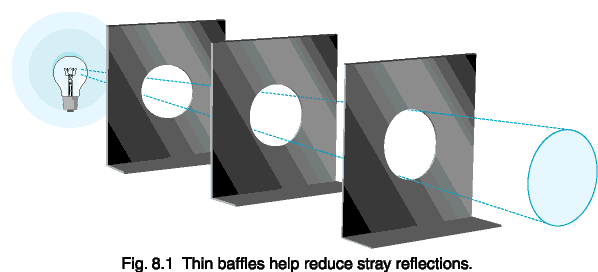
Baffles, for example, greatly reduce the influence of stray light reflections. A baffle is simply a sharp edged hole in a piece of thin sheet metal that has been painted black. Light outside of the optical beam is blocked and absorbed without affecting the optical path.
Multiple baffles are usually required in order to guarantee that light is trapped once it strikes a baffle. The best light trap of all, however, is empty space. It is a good idea to leave as much space between the optical path and walls or ceilings as is practical. Far away objects make weak reflective sources because of the Inverse Square Law. Objects that are near to the detector, however, have a significant effect, and should be painted with “black velvet” paint or moved out of view.
A shutter, door, or light trap in one of the baffles allows you to measure the background scatter component and subtract it from future readings. The “zero” reading should be made with the source ON, to maintain the operating temperature of the lamp as well as measure light that has defeated your baffling scheme.
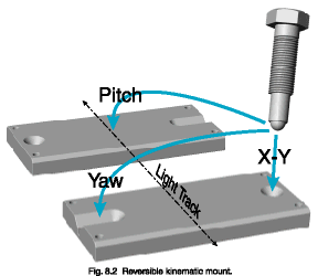
To make a kinematic fixture, cut a cone and a conical slot into a piece of metal using a 45° conical end mill (see fig. 8.2). A kinematic mount is a three point fixture, with the third point being any planar face. The three mounting points can be large bolts that have been machined into a ball on one end, or commercially available 1/4-80 screws with ball bearing tips (from Thorlabs, Inc.) for small fixtures.

A three legged detector carrier sitting on a kinematic mounting plate
is the most accurate way to interchange detectors into the optical path,
allowing intercomparisons between two or more detectors
.
