


The perspective projection from Euclidean 3-space to an image is represented as

 is a
homogeneous
is a
homogeneous  camera projection matrix (11 dof) with the
decomposition
camera projection matrix (11 dof) with the
decomposition

The algorithm for camera calibration has two parts:
 from a set of points with known
3D positions
and their measured image positions.
from a set of points with known
3D positions
and their measured image positions.
 into
into  and
and  via the
  decomposition.
1. Compute the matrix  : Use correspondences between
3D points
: Use correspondences between
3D points  and their 2D images
  to determine the matrix
  .
.
 .
.

multiplying out

 ) correspondences,
a linear solution can be obtained for
) correspondences,
a linear solution can be obtained for  from the
set of 2n linear simultaneous equations (cf computation
of a projective transformation):
from the
set of 2n linear simultaneous equations (cf computation
of a projective transformation):  ,
where
,
where  is the 12-vector representation of the projection
matrix
is the 12-vector representation of the projection
matrix  , and
, and  is a
is a  matrix.
The solution is the eigenvector with least eigenvalue of
matrix.
The solution is the eigenvector with least eigenvalue of  .
.

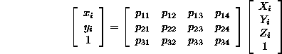
Example - Calibration Object
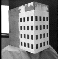
Determine accurate corner positions by
The final error between measured and projected points is typically less than 0.02 pixels.
2. Decompose  into
into  and
and  :
:
The first  submatrix,
  , of
, of  is the
product (
is the
product ( ) of an upper triangular and rotation matrix.
 into
into  using
the
using
the  matrix decomposition. This determines
 and
and  .
.

Note, this procedure produces a matrix with an extra parameter k

with  , and
, and  the angle between the image axes.