paper submitted: october 25th, 2000
![]()
paper submitted: october 25th, 2000
 |
 |
 |
|
|
Josep Lladós,
Enric Martí |
|||
1. Introduction
2. Vectorization
3. Recognition of Building Elements
4. An example of architectural floor plan interpretation
Graphics recognition is a pattern recognition field that closes the loop between paper and electronic documents. Thus, while all the graphic design systems are able to accurately edit and print out their electronic diagrams, the reverse step, i.e. the automatic conversion from a paper-based document to an electronic CAD-readable format, is still a challenge. Architectural floor plan analysis is one of the application domains of the graphics recognition field.
The interpretation of architectural plans is a recent research activity [2,3,10,12,14,16,22]. It has been focused on two kinds of printed plans and hand drawn sketches. the goal of the first activity is the conversion of printed plans into a CAD-readable format for storage and edit purposes. Efficient vectorization engines are at the heart of this kind of systems. The interpretation of hand drawn sketches represents an alternative CAD-input technique and conveys distortion-tolerant symbol recognition processes.
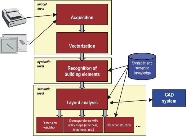
According to the general framework of any graphics recognition system, an architectural floor plan analysis system is organized in three stages (see Fig. 1). Firstly, the lexical level is concerned about the extraction of the graphic primitives that compose the drawing, such as lines, arcs and regions. Usually, the lexical level involves a preprocessing step in which operations as binarization, noise removal, thinning, etc. are also performed. Discrimination of text from graphics is also carried out in this step. The second stage is the syntactic level which establishes structural relations between primitives grouping them to provide a symbolic representation of the input document. Finally, the high-level processing is the semantic level. The aim of the semantic phase is to understand the document, that is analyzing relationships among symbolic mid-level structures and assembling them into high level entities with a particular meaning depending on the domain of the specific application. In the case of architecture, these entities can be rooms, electrical network elements, furniture, etc.
 |
Two activities highlight from the former schema: vectorization and symbol recognition. In the following sections we overview these two steps.
Vectorization, or raster-to-vector conversion, consists in converting a scanned image to a vectorial format suitable for further analysis. It is not an specific step for architectural plan analysis, but one of the central interests of graphics recognition community. Two major vectorization approaches can be stated: those that are based on skeleton or medial axis computation, and others that do not thin the image but match opposite contours of lines. Tombre and Tabonne in [21] rencently compared these two families of vectorization methods.
Skeleton based methods consist in computing the medial axis with an iterative thinning or distance transform algorithm. Afterwards, the skeleton is approximated by straight lines, arcs or higher order primitives such as splines. Many skeleton-based vectorization methods have been proposed throughout the years (e.g. [1,5,18,20]), they key issues are the algorithm used to compute the skeleton and the polygonal approximation. The main drawback of these methods is that they tend to introduce distortions at line end points and junctions. However, their robustness when dealing with complex diagrams make them to be the most used method in vectorization packages.
Concerning to contour-matching approaches [11,13,19], they are based in finding the line contours of the plan, polygonally approximate them, match the corresponding vectors in terms of slope and distance criteria and compute the medial line from the pairs of matched vectors. They are more accurate in finding the junctions than skeleton-based methods. The difficulty of contour-matching methods appears in complex diagrams in which one-to-many and many-to-one matching hypotheses appear, for example in case of arcs approximated by polygons, and some heuristics have to guide the correspondence process. Although there are still several improvements to make, the field is mature enough to ask for a robust and universal vectorization method able to work on different domains and with the minimum set of parameters [20]. Probably, one of the improvements in the vectorization process depends on an efficient combination of both families of methods.
Vectorization is not enough to fully understand a plan and convert it to a CAD readable format for further edition. Vectors are only a set of primitives with geometrical and topological attributes. Subsequent intelligent processes are necessary to detect and classify symbolic structures that, according to diagrammatic notations given by the architects, represent doors, windows, walls, etc. In the next section we overview the key issues involved in the recognition of building elements.
In architectural drawings, the recognition of higher level entities such as walls, doors, windows, furniture, stairs, etc. allows the interpretation of the document and, hence, its conversion to a CAD environment in which perform features as design modifications, validations, 3D visualization and virtual navigation inside the building. Building element recognition is a pattern recognition activity and, particularly, a symbol recognition problem. Symbol recognition is currently an intensive research activity. It is at the heart of most graphics recognition systems that have been developed. The reader is referred to recent surveys as [4,6,8] to further study on general methodologies for symbol recognition. Although many symbol recognition methods are available, it is difficult to find a general approach that covers different domains. Authors tend to develop techniques restricted to particular domains and costly to be reused in other domains. In the field of architectural plan interpretation, the most outstanding contributions use structural pattern recognition approaches.
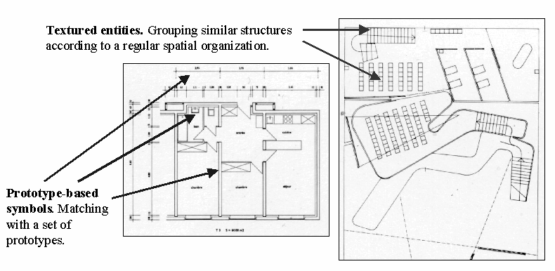
Two major symbol structures can be categorized in architectural drawings: prototype-based symbols and texture-based symbols (see Fig. 2). Examples of symbols characterized by a prototype are doors and windows. The recognition is performed by a pattern matching procedure. On the other hand, architectural drawings often contain symbols represented by an structured texture as hatching or tiling. Such structures represent walls, floors or stairs.
 |
The more widespread structural method for symbol recognition in architectural plan analysis is graph matching [2,16]. Both, vectorized plans and model symbols are represented by attributed graph structures. Since noisy input documents, and errors in preprocessing and vectorization steps introduce distortions in structures, an error tolerant graph matching procedure is required. Graph-edit procedures and rule-based languages are the most common techniques to solve the problem. Thus, an inexact subgraph isomorphism algorithm finds the minimum cost transformation, in terms of elemental graph edit operations (node and edge insertion, deletion and substitution), from a graph representing the symbol prototype to a graph representing the input document. This approach, in addition to distortion tolerance, does not require a presegmentation step, i.e. symbol recognition is performed directly on the input document and hence, involves symbol segmentation. This is specially useful in architectural plan analysis because symbols are not easily segmentable. However, the computation of the graph edit distance is computationally expensive, specially with complex symbols.
Other approaches work on presegmented symbols. Syntactic and deformable template matching are well known recognition methods when symbols are able to be segmented. Syntactic methods represent symbols by a grammar, usually a graph or a web grammar, and perform the recognition by a parsing procedure. Such syntactic approaches are often used to recognize the dimensioning symbols [7,9,17]. Deformable template matching was used in [22] to recognize presegmented hand drawn architectural symbols. To modelize the distortion involved in hand drawn sketches, the recognition is formulated as an energy minimization problem in a bayessian framework. The energy is defined through the combination of internal energy, which measures fidelity to ideal shape, and external energy which measures the degree of fitness between the deformed symbol and the image.
Concerning to entities characterized by an structured texture, they appear in architectural drawings representing walls, stairs, tiles, roofs, etc. The most usual patterns are hatching and tiling. Hatched pattern detection is based on clustering parallel lines having the same slope angle and sorting them along a direction normal to their slope angle. Besides hatched patterns, textures based on regular repetitions of polygonal shapes are eventually used. To modelize them, syntactic approaches such as array or web grammars are suitable tools. The presence of this type of textures can be found in architectural drawings to represent a tiled floor. In our architectural plan interpretation system [15], we have developed a Hough-based method to detect hatched patterns representing walls, and a graph clustering approach based on a polygon similarity criterion, for tiled patterns.
In Fig. 3 we show an example of the interpretation of a hand drawn architectural floor plan. Figure 3(a) shows the scanned document, A skeleton-based algorithm gives the vectors of Fig. 3(b). Afterwards, the building elements are recognized in two steps, namely, structures characterized by a hatched pattern (Fig. 3(c)) and prototype-based symbols (Fig. 3(d)). Finally, the reconstructed plan is shown in Fig. 3(e).

|

|

|
 |
 |
| (a) | (b) | (c) | (d) | (e) |
The most recent version of this article is here.