Figure 3: Surface decomposition: a cube with a hole


If object perception is primarily dependent on surface perception, then perhaps a surface boundary representation of a solid object is the natural choice for a computer vision system. Active vision systems do in general provide a surface-based scene description; raw depth data is pre-processed and segmented to form planar, quadric or even more complex surface patches.
The enclosing surface or boundary should unambiguously specify the object. In Figure 3, below, a solid object has been decomposed into a set of planar and quadric surfaces.

Figure 3: Surface decomposition: a cube with a hole
A general surface in 3 dimensions may be written as

If the gradient vector  exists, is continuous, and is defined for every point on the surface, then S is a smooth surface. B-reps can use progressively more complex representations to describe objects. In the simplest case, an object may be approximated by planar facets of the form,

For a planar surface the shape is invariant. The coefficients (A,B,C) define the direction of the unit normal to the surface and D specifies the distance of the plane from the origin of the coordinate system. Quadric surfaces require 10 coefficients,

4 coefficients are needed to describe the shape of the surface, whereas 6 parameters are needed to define the position and orientation of the surface in 3D space. Thus if a quadric surface is properly rotated and translated at least 6 of it's coefficients will be zero, and all quadric surfaces can then be classified as one of the following types, using the non-zero coefficients
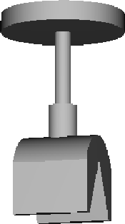
Commonly, computer vision systems are built using much simpler representations, for example based on a subset consisting of planar, cylindrical, spherical and conical surfaces. In that case, it may be preferable to use a typed definition of surfaces, rather than a more general quadric form. Considering the object in Fig 2: A solid model of an optical stand we can show an equivalent surface representation in Figure 4, below. This is ray-traced from a surface model whose principal components are shown in Figure 5: A schematic representation of the surface model. The model contains a lot of additional information, including for example adjacency and bounding contour information.

Figure 4: Surface definition of the optical stand
a subsection of the stand surface definition
OBJECT Stand
AREA 95587.710253
XMIN -50.000000
YMIN -50.000000
ZMIN 0.000000
XMAX 50.000000
YMAX 50.000000
ZMAX 165.000000
RADIUS 123.104283
GRAVITY-CENTRE 0.032828 0.000000 114.137485
COLOR 192 192 192
DIFFUSION 1.000000
SPECULARITY 0.000000
TRANSMITTANCE 0.000000
PLANAR-PATCHES
plp001 plp003 plp004 plp005 plp006 plp007 plp008 plp009
plp105 plp106 plp107
CYL-PATCHES
cyp004 cyp003 cyp002 cyp001
SPH-PATCHES NO
CON-PATCHES NO
UNKNOWN SURFACES NO
SEGMENTS
sgt279 sgt282 sgt283 sgt284 sgt285 sgt286 sgt287 sgt288
sgt289 sgt290 sgt291 sgt292 sgt293 sgt295 sgt296 sgt297
sgt298 sgt299 sgt301 /
CIRCULAR-ARCS
car007 car006 car005 car004 car003 car002 car001
UNKNOWN CURVES
apc022
etc.
PL-PATCH <plp107
LABEL plp107
AREA 628.221672
NORMAL 0.000000 0.000000 1.000000
REF-POINT 0.000000 0.000000 90.000000
POINTS
pnt089 pnt088 pnt073 pnt074 pnt075 pnt076 pnt061 pnt062
pnt063 pnt090 pnt086 pnt085 pnt084 pnt083 pnt082 pnt081
pnt079 pnt080 pnt064 pnt065 pnt066 pnt067 pnt068 pnt069
pnt070 pnt071 pnt072 pnt077 pnt078 pnt087
ADJ-FACES
plp043 plp038 plp037 plp036 plp035 plp034 plp033 plp044
plp045 plp046 plp047 plp040 plp018 plp017 plp023 plp022
plp021 plp020 plp013 plp012 plp039 plp048 plp049 plp050
plp051 plp052 plp053 plp054
SEGMENTS
sgt182 sgt195 sgt196 sgt197 sgt198 sgt199 sgt200 sgt201
sgt202 sgt181 sgt179 sgt176 sgt174 sgt184 sgt185 sgt186
sgt187 sgt188 sgt189 sgt190 sgt191 sgt192 sgt193 sgt172
sgt170 sgt168 sgt166 sgt164 sgt162 sgt159
CARC-EDGES
car005 car004
APC-EDGES NO
PART-OF NIL
IN-FAC-SURF fsf010
PRIM plp107
COLOR -1 -1 -1
SPECULARITY -1.000000
DIFFUSION -1.000000
TRANSMITTANCE -1.000000
etc.
CYL-PATCH <cyp004
LABEL cyp004
AREA 9983.477807
SIGN 1
DIR 0.000000 1.000000 0.000000
REF-POINT 0.000000 0.000000 27.521708
RADIUS 37.478292
SEGMENTS
sgt265 sgt263 sgt267 sgt203 sgt220 sgt261 sgt221 sgt218
sgt216 sgt214 sgt212 sgt209 sgt223 sgt225 sgt211 sgt206
sgt270 sgt277 sgt275 sgt278 sgt271 sgt259 sgt257 sgt255
sgt252 sgt266 sgt272 sgt273 sgt279 sgt280 sgt281 sgt301
sgt294 sgt300 sgt236 sgt237 sgt233 sgt234 sgt230 sgt231
sgt227 sgt228 sgt249 sgt250 sgt246 sgt247 sgt243 sgt244
sgt239 sgt241
CARC-EDGES
car007 car006
APC-EDGES
apc022
APPROX-BY
plp016 plp019 plp032 plp015 plp011 plp014 plp010 plp002
plp028 plp029 plp030 plp031 plp024 plp025 plp026 plp027
P1 0.000000 -30.000000 27.521708
P2 0.000000 30.000000 27.521708
COLOR -1 -1 -1
SPECULARITY -1.000000
DIFFUSION -1.000000
TRANSMITTANCE -1.000000
etc.
Although, a B-rep may include only surface definitions, and these may unambiguously define the object, the extent of surfaces is usually defined in some way, for example by defining the enclosing contour. B-reps or surface representations may include both surfaces and space curves, and typically they may also include links or pointers between them to define adjacency and connectivity. For example, the intersection of a plane and a cylinder may be an elliptical space curve, which is adjacent to both the original surfaces which are, in turn, adjacent (separated by the ellipse). This can be used for matching against surfaces ( from depth data ), space curves ( from depth data ) or two dimensional boundaries in perspective projection ( from intensity data).


[ Volumetric representations |
Wire frame representations ]
Comments to: Sarah Price at ICBL.