Figure 1 The MU5 Processor
Figure 1 The MU5 Processor
Figure 2 shows (in blue) the basic hardware required in the Primary Operand Unit to implement the primary operand accessing facilities of the instruction set (see The MU5 instruction format in the section on Instructions and Addresses) and the various stages of operation involved in processing a typical instruction. Instructions are received from the Instruction Buffer Unit (IBU) into registers DF (function) and DN (name). The first action is the decoding of the instruction to select the contents of the appropriate base register (NB, XNB or SF) and the name part of the instruction. For access to a 32-bit variable, the name is shifted down one place relative to the base and the least significant digit is used later to select the appropriate half of the 64-bit word obtained from the Name Store.
Figure 2 The MU5 Primary Operand Unit
In the second stage the name and base are added together to form the address of a 64-bit word. This address is concatenated with the 4-bit Process Number (PN) and presented to the Associative Field of the Name Store in the third stage. If the address is found, access is made in the fourth stage to the 64-bit word in the Name Store Value Field (if the required address is not in the associative store, the non-equivalence actions described in The MU5 Name Store in the section on Storage Hierarchies must be initiated). The fifth stage of processing is the assembly of the operand. A 32-bit integer, for example, may be taken from either half of the 64-bit store word, but must always appear at the least significant end of the data highway when presented to a succeeding unit. Registers FN and HI form the input to the highway which links PROP to other units in the processor and register HO is connected to one of the outputs of this highway in order to receive operands resulting from store orders.
During the design of MU5, performance considerations led to the adoption of a pipeline structure for PROP. The additional components needed to create this pipeline are shown in pink in Figure 2. The time taken for the PROP pipeline to process one instruction is slightly longer than it would have been in a non-pipelined version but the rate of processing is, in principle, about five times greater. As mentioned in Principles of pipeline concurrency, however, the average instruction execution rate is reduced by the effects of different instruction types and some instructions cause additional complications for the designers of the hardware.
Figure 3 Clocking Signals in the MU5 Primary Operand Unit
Within the PROP pipeline, the clock signals, though staggered, were synchronous. Between PROP and its successor units, however, the interconnection was asynchronous. Once an instruction had reached HI, PROP waited until the instruction had been accepted by the appropriate successor unit before taking any further action. When it had been accepted, the Control Register was updated for that instruction and all other instructions in the pipeline moved along one stage. Instructions therefore proceeded through PROP in a series of beats, the rate at which these beats occured being determined by the maximum operating rate of PROP and the acceptance rates of the succeeding units. The generation of a beat was initiated by the setting of a data gone flip-flop (Figure 4) which when any other necessary conditions at the end of the PROP pipeline had been satisfied, allowed a clock signal to propagate through the pipeline. The progress of one clock through the pipeline is shown in red in Figure 3.
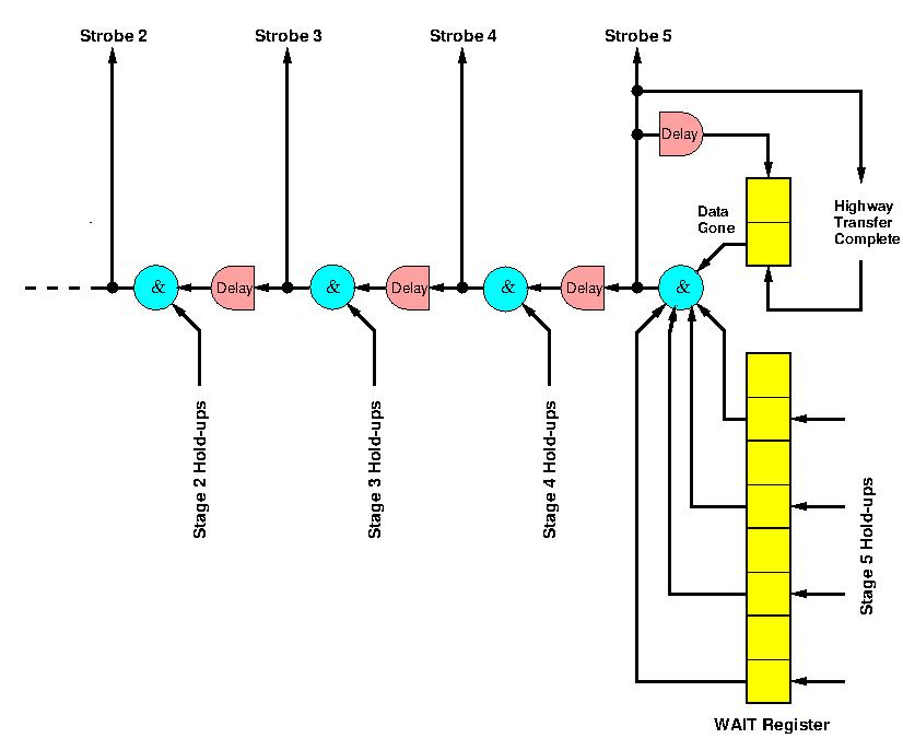
Figure 4 The Pipeeline Delay Chain
The shaded portions of Figure 3 show how an instruction progressed through the PROP pipeline. It was first copied from the Instruction Buffer Unit output into DF and DN (function and name respectively) and the Decode 0 logic carried out the decoding of the instruction necessary to control the first stage. The decoding logic was spread out in the pipelined version into separate decoders for each stage. In many cases the necessary decoding could not be carried out in sufficient time to control the action of a given stage, so it was carried out in the previous stage and the various control signals appeared as additional function digits, along with the original function, as inputs to the following stage.
Pipeline clock signal were timed to arrive no earlier than when the outputs of the first stage had settled and were ready to be strobed into the registers F1 (function), NM (name) and BS (base). The addition of name and base now took place and when the next pipeline clock arrived, the result was copied into IN (the Name Store Interrogate Register) and the function into F2. The output of IN was concatenated with PN, the Process Number, to form the input to the associative field of the Name Store. The result of the association was then copied into the Line Register (LR) and the function into F3. The output of LR accessed the line in the Value Field containing the required operand. The Value Field output was copied into the Value Field register (VF) and the function into F4. In the final stage the operand was assembled from VF (e.g. a 32-bit operand could be taken from either half of the 64-bit word read from the Name Store) and copied into the Highway Input register (HI), ready to be sent to the next unit.
partial results were stacked by the use of the *= (stack and load) function. They were later unstacked by use of the operand form STACK (see the MU5 Instruction Format in the section on Instructions and Addresses). Stacked operands were therefore contained in the MU5 Processor storage system in exactly the same way as names, their addresses being generated relative to the Stack Front register (SF), which pointed to the most recently stacked operand within the Name Segment. Thus SF was advanced by both the *= function and functions concerned with procedure entry (STACK and STACK LINK), and all these functions required two operand accesses to be made. Hence they were divided into two phases.
For the STACK function, for example, an access was first made for the specified operand followed by an access to the stack, while for the *= order the first access was to the stack, in order to store the content of the specified register, and the second was for the operand. For stack writes the name/base adder was used to create the address SF+2 and at the same time SF was updated to this new value. The two phases of these orders were distinguished by extra digits carried through the pipeline with the function. These digits overrode the normal operand accessing mechanisms when access to the stack was required and also prevented the incrementing of the Control Register when the first phase reached HI.
The implementation of this stack mechanism within a pipeline gave rise to additional problems in relation to branches and jumps (control transfers). An order implicitly changing SF did so while there were still several orders ahead of it in the pipeline. Some of these did not reach the Control Point (the point in the pipeline at which the Control Register was updated), and were therefore not completed. Any one of these orders could be a control transfer order requiring that partially processed orders behind it in the pipeline, including any orders that modified SF, be abandoned. When this situation occured, the SF Register could be left containing an incorrect value. The correct SF value could have been maintained by preventing overlap in such situations, but this would have caused serious performance degradation. The alternative solution adopted was to allow the SF register to change as and when required and to propagate forward any new value for SF in registers S3, S4 and S5 (shown in magenta in Figure 2). When the Control Register was updated for each order, the value in S5 was copied into S6. Therefore, when a control transfer occured the value in S6 was known to be correct and was used to restore SF. In a non-pipelined computer this situation would not arise since each instruction would be completed, and all register values would be updated, before the next instruction could begin. A particular consequence of this is that an order which writes the contents of a programmable register to store in a non-pipelined computer can proceed without delay, since the register contents are guaranteed to be correct and available at the start of the order. This is not generally true in a pipelined computer where operand accesses are made several pipeline stages ahead of the programmable register into which the results of the operations involving those operands will be loaded. This leads to the read-after-write problem.
Whenever a B => name order entered Stage 4 of the PROP pipeline, the content of the PROP Line Register was preserved, for later use, in an additional register BW, and the order proceeded normally through the pipeline without causing a hold-up and without impeding orders following, except as described below. Execution of a => order in the B-unit involved sending the result to the HO register in PROP. When it arrived the PROP pipeline was held up before the next pipeline clock was generated (MU5 was an asynchronous systems), and the information held in register BW was used to select the appropriate line in the Value Field of the Name Store so that the value in HO could be written into it. The additional information needed to select one-half of the line for overwriting was held in the F2 Function Register, together with a B => outstanding digit which indicated that the BW Register was in use. When the action of writing into the store has been completed, the B => outstanding digit was re-set and the pipeline re-started.
While the B => outstanding digit was set, two pipeline hold-ups could occur, one at Stage 2 and one at Stage 4. These hold-ups were typical of a number which could arise in the pipeline because some necessary information (such as the B register value for the B => name order) was not immediately available. Apart from hold-ups which arose from the fifth stage, they could not be detected in time for the next pipeline to be inhibited and therefore operated independently of the clock generating logic, by simply preventing subsequent clock beats from propagating back beyond the stage from which they arose, and by causing dummy orders to be propagated forwards. The hold-up at Stage 2 occured if a second B => name instruction entered that stage, while the B => outstanding digit was set, because the BW register could only deal with one outstanding order at a time. This hold-up prevented subsequent clock beats from propagating back beyond the input registers to Stage 3 (F3, etc.) and caused dummy orders to be copied into Stage 3. The hold-up at Stage 4 occured if an instruction tried to access the same line in the Name Store as that indicated by BW. This is an example of the read-after-write problem found in almost all instruction processing pipelines [1] and was a further consequence of the fact that the B register value was not available for writing into store when the B => name order reached the Name Store. The hold-up prevented subsequent clock beats from propagating back beyond the input registers to Stage 5 (F5, etc) and caused dummy orders to be copied into Stage 5. Both these hold-ups were automatically released when the B => outstanding digit was re-set, or if the contents of the pipeline were discarded by the action of a control transfer before the B => order had left the end of PROP. If a control transfer occured after a B => order had left the end of PROP, then the store updating action was still carried out since the Control Register would have been incremented for this order.
Branch instructions are a major problem in pipelined instruction processors, since if the branch is taken all the instructions pre-fetched and partially executed in the pipeline must normally be discarded. This can not only cause serious delays in instruction execution, but also requires the designer to ensure that no irrecoverable action is taken during the partial execution of instructions ahead of the Control Point. An example of the latter is the implementation of the stacking mechanism in PROP. Various techniques have been used in high performance computers to overcome the delay problems caused by control transfers (see under Instruction Buffers). In MU5 the Instruction Buffer Unit incorporated a prediction mechanism that, following the first execution of a particular control transfer, attempted to supply the correct sequence of instructions to the pipeline behind subsequent occurrences of that control transfer, so that if the branch was taken there was no delay in continuing instruction execution. This system offered a performance advantage, because unconditional transfers always branch and a high proportion of conditional control transfers are loop closing instructions which branch more often than not.
When a control transfer instruction reached the end of PROP an out-of-sequence digit accompanying the following instruction was examined. If set this digit indicated that the instruction was the start of a predicted jump-to sequence, and if the control transfer was unconditional or conditional and the condition was met, instruction execution could proceed as soon as the Control Register had been updated. This also happened if the out-of-sequence digit was not set and the condition for a conditional transfer was not met. If the out-of-sequence digit was not set following an unconditional transfer or a conditional transfer for which the condition was met, however, or if the out-of-sequence digit was set and the condition for a conditional transfer was not met, then all instructions in the pipeline before the Control Point (those in PROP and in the Instruction Buffer Unit) had to be discarded, by the setting of their dummy order bits, and a long delay was incurred while the new jump-to sequence of instructions was fetched.
| Execution | Compilation | ||||
| Type of Order | Excess time | Frequency (%) | Time Added | Frequency (%) | Time Added |
| Multi-length | 50 | 56.0 | 27.9 | 45.7 | 22.8 |
| B Store | 100 | 6.2 | 6.2 | 9.1 | 9.1 |
| Base Manipulation | 450 | 5.1 | 23.0 | 8.4 | 37.8 |
| Predicted Control Transfer | 100 | 8.7 | 8.7 | 8.0 | 8.0 |
| Unpredicted Control Transfer | 1350 | 4.5 | 60.7 | 10.5 | 141.8 |
| Name Store Miss | 1180 | 3.5 | 41.3 | 11.9 | 140.4 |
| Total net time added | 167.8 | 359.9 | |||
| Average instruction time | 217.8 | 409.9 | |||
For both execution and compilation the longest delays are due to unpredicted control transfers and Name Store non-equivalences. The significant difference in performance between these two types of activity is due largely to the data-dependent nature of the compilation process which involves many alternative processing sequences. Name Store delays are largely a consequence of the organisation of the storage hierarchy (see under The MU5 Name Store), whereas the delays caused by control transfers, B-store orders and base manipulation orders are directly attributable to the difficulties inherent in processing sequentially dependent instructions in a pipeline, and those due to multi-length orders are consequences of the particular organisation chosen for the IBU-PROP interface. In each case, however, improvements could be made which would reduce these delays. Many of the decisions taken during the design of MU5 were based, inevitably, on inadequate information about instruction usage, and in a commercial environment changes almost certainly would have been made to subsequent models in the light of experience gained from what was essentially a prototype design.