

The files for the MIPS1 model can be downloaded from mips_v1.3.zip
The files for the MIPS2 model can be downloaded from mips_v2.3.zip
These MIPS models, based on an earlier model of the DLX architecture, were built by David Dolman during tenure of a University of Edinburgh College of Science & Engineering Strachan Scholarship.
Instructions on how to use HASE models can be found at Using HASE Models.
The Integer Unit receives its operands from the Instruction Decode Unit, which is closely coupled to the Registers. These consist of 32 Integer Registers. The results from both arithmetic/logic and load instructions are returned to the Registers by the Write Back Unit.
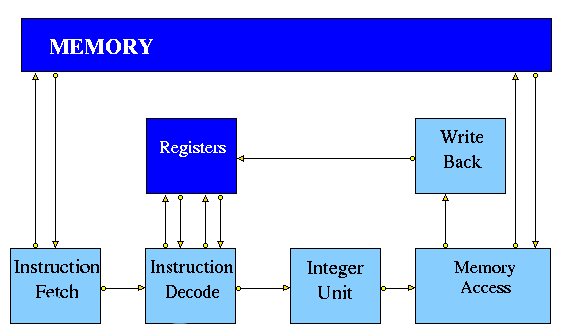
Figure 1. Typical Simple MIPS Pipeline
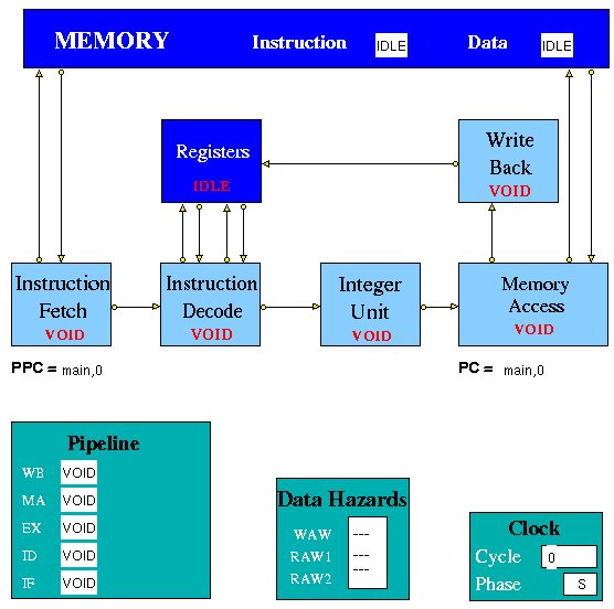
The PC and PPC each have two fields: a label and an offset. At the start of the simulation, the Memory entity creates a table of labels and their absolute addresses. When fetching instructions, the Memory entity adds the offset to the label to get the absolute address of the instruction.
For a branch instruction, the use of a label differs from the use of an offset value. When an integer offset is used, the offset value in the instruction is added to the current value of the PC offset field. When a label is used, the label in the instruction is copied into the PC label field and the offset field is set to 0. Similarly, when a jump instruction uses an integer value, the offset field in PC is set equal to this value and the label field is set to 'main'. When a jump instruction uses a label, the label in the instruction is copied into the PC label field and the offset field is set to 0.
The initial value of the label in the PPC and PC is 'main'; this is the starting address of the program (instruction memory address 0).
Note: Despite labels occupying their own line they do not count as instructions and therefore take up no instruction memory. This is an important consideration when using an (absolute) jump or (relative) branch, as line numbers will not reflect instruction addresses. Therefore it is advisable not to use a mixture of labels and offset values in one program.
| Instruction | Description | Example | Result |
| LB | Load Byte | LB R3 1(R0) | Loads Byte from memory location 1 |
| LBU | Load Byte Unsigned | LBU R4 1(R0) | Loads Byte Unsigned from memory location 1 |
| SB | Store Byte | SB R1 1(R0) | Stores Byte in R1 into memory location 1 |
| LH | Load Halfword | LH R4 2(R0) | Loads Halfword from memory location 2 into R4 |
| LHU | Load Halfword Unsigned | LHU R4 2(R0) | Loads Halfword Unsigned from memory location 2 into R4 |
| LUI | Load Upper Immediate | LUI R1 124 | Load 124 in the the upper half of regester R1 |
| SH | Store Halfword | SH R5 6(R0) | Stores Halfword from R5 into memory loction 6 |
| LW | Load Word | LW R4 8(R0) | Loads Word from data memory location word 8 into R4 |
| SW | Store Word | SW R3 16(R0) | Stores Word in R3 into location 16 in data memory |
Table 1a. Load/Store Instructions
| Instruction | Description | Example | Result |
| ADDI | Add Immediate Word | ADDI R1 R2 -4 | Store R2 + -4 in R1 |
| ADDIU | Add Immediate Unsigned Word | ADDIU R1 R2 16 | Store R2 + 16 in R1 |
| ADD | Add Word | ADD R1 R2 R3 | Store R2 + R3 in R1 |
| ADDU | Add Word Unsigned | ADD R1 R2 R3 | Store R2 + R3 in R1 |
| SUB | Subtract Word | SUB R1 R2 R3 | Store R2 - R3 in R1 |
| SUBU | Subtract Word Unsigned | SUB R1 R2 R3 | Store R2 - R3 in R1 |
| SLT | Set on less than | SLT R1 R2 R3 | If R2 is less than R3 set R1 to be 1 else set it to 0 |
| SLTI | Set on less than Immediate | SLTI R1 R2 5 | If R2 is less than 5 then set R1 to 1 else set it to 0 |
| SLTU | Set on less than Unsigned | SLTU R1 R2 R3 | If the unsigned value of R2 is less than the unsigned value R3 set R1 to 1 else set it to 0 |
| SLTIU | Set on less than Immediate Unsigned | SLTIU R1 R2 6 | If the R2 is less than 6 (after sign extension) set R1 to 1 else set it to 0 |
Table 1b. Arithmetic Instructions:
| Instruction | Description | Example | Result |
| AND | And | AND R1 R2 R3 | Stores result of R2 AND R3 into R1 |
| ANDI | And Immediate | ANDI R1 R1 19 | Stores the result of R1 AND 19 back into R1 |
| OR | Or | OR R1 R2 R3 | Stores result of R2 OR R3 into R1 |
| ORI | Or Immediate | ORI R1 R1 128 | Stores the result of R1 OR 128 back into R1 |
| XOR | Exclusive Or | XOR R1 R2 R3 | Stores result of R2 XOR R3 into R1 |
| XORI | Exclusive Or Immediate | XORI R1 R1 64 | Stores the result of R1 OR 64 back into R1 |
| NOR | Nor | NOR R1 R2 R3 | Stores result of R2 NOR R3 into R1 |
| SSL | Shift Word Left Logical | SSL R1 R2 4 | Shift R2 4 bits to the left and store in R1 |
| SRL | Shift Word Right Logical | SRL R1 R2 2 | Shift R2 2 bits to the right and store in R1 |
| SRA | Shift Word Right Arithmetic | SRA R3 R4 2 | Arithmrticaly shift R4 2 bits right and store in R3 |
| SLLV | Shift Word Left Logical Varable | SLLV R1 R2 R3 | Shift R2 left by R3 bits and store in R1 |
| SRLV | Shift Word Right Logical Varable | SRLV R1 R2 R3 | Shift R2 right by R3 bits and store in R1 |
| SRAV | Shift Word Right Arithmetic Varable | SRAV R1 R2 R3 | Shift R2 right arithemeticaly by R3 bits and store in R1 |
Table 1c. Logical Instructions:
| Instruction | Description | Example | Result |
| J | Jump | J 8 | Jump to instruction 8 |
| JR | Jump Register | J R1 | Jump to the instruction number held in R1 |
Table 1d. Jump Instructions:
| Instruction | Description | Example | Result |
| BEQ | Branch on equal | BEQ R1 R2 4 | Branch forward 4 instructions if R1 and R2 are equal |
| BNE | Branch on not equal | BNE R1 R2 8 | Branch forward 8 instructions if R1 and R2 are not equal |
| BLEZ | Branch on less than or equal to zero | BLEZ R2 -2 | Branch back 2 instructions if R2 is less than or equal to zero |
| BGTZ | Branch on greater than zero | BGTZ R2 -2 | Branch back 2 instructions if R2 is greater than zero |
| BLTZ | Branch on less than zero | BLTZ R2 3 | Branch forward 3 instructions if R2 is less than zero |
| BGEZ | Branch on greater than or equal to zero | BGTZ R2 5 | Branch forward 5 instructions if R2 is greater than or equal to zero |
| BLTZAL | Branch on less than zero and link | BLTZAL R2 3 | Branch forward 3 instructions if R2 is less than zero |
| BGEZAL | Branch on greater than or equal to zero and link | BGTZAL R2 5 | Branch forward 5 instructions if R2 is greater than or equal to zero and link |
Table 1e. Branch Instructions:
| Instruction | Description | Example | Result |
| BREAK | Breakpoint | BREAK | Halt |
| NOP | No Operation | NOP | No operation |
Table 1f. Other Instructions:
 |
 |
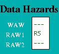 |
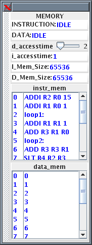
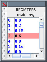
Figure 3. Memory, Registers and Data Hazards Displays
The Memory receives instruction requests from the Instruction Fetch Unit and Read/Write requests from the Memory Access Unit and, as appropriate, either returns the contents of the requested memory word to the requesting unit or updates it. It checks for invalid addresses, and sets an error flag in the Scoreboard if either occurs. The size of each array is determined by parameter of the Memory entity, set to 256 as a default.
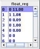
Data hazards are handled through Use bits. Each register has a Use bit which is set when an instruction that will write to the register is issued and reset when the result is written to the register. In the HASE MIPS model the registers are implemented as C++ structs with two fields: Use bit and value. In the Register Display Window shown in Figure 3, for example, Register 5 has its Use bit set and has a value of 16, while all the others are in the reset state. Before accessing a source or destination register, the Instruction Decode Unit invokes a class in the Registers entity which reads the relevant Use bit. If the Use bit for a Register required as a source operand is set, then there is a RAW hazard, as shown for Register 5 in the Data Hazards Display window. If the Use bit for a Register required as a destination operand is set, then there is a WAW hazard.
At the start of Clock phase 0 each pipeline entity sends an (untraced) packet to the Pipeline Display entity containing a copy of the instruction and status fields from within its own input packet. If the instruction is valid, the Pipeline Display entity 'prints' the instruction to the appropriate place on the screen; if the instruction is not valid it prints 'VOID'.
| Instruction | Result/Comment |
| ADDI R2 R0 15 | R2 = R0 + 15 (=15) |
| ADDI R1 R0 1 | R1 = R0 + 1 (=1) |
| loop1: | Label - does not count as an instruction |
| ADDI R1 R1 1 | R1 = R1 + 1 (increment R1 by 1) |
| ADD R3 R1 R0 | R3 = R1 + R0 (copy R1 to R3) |
| loop2: | Label - does not count as an instruction |
| ADD R3 R3 R1 | R3 = R3 + R1 (increment R3 by R1) |
| SLT R4 R2 R3 | R4 = 1 if R2 < R3 else R4 = 0 |
| BNE R4 R0 done | Branch to done if R4 != R0 (R4 != 0) |
| SLL R5 R3 2 | R5 = R3 Left shifted 2 places |
| J loop2 | Branch to loop2 |
| SW R0 0(R5) | Delay slot: Store R0 at memory location R5 |
| done: | Label - does not count as an instruction |
| BNE R1 R2 loop1 | Branch to loop1 if R1 != R2 |
| NOP | Delay slot: No operation |
| BREAK | End the simulation |
| NOP | No operation |
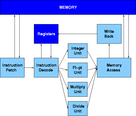
Figure 4. MIPS with Parallel Function Units
The Execution Units receive their operands from the Instruction Decode Unit, which is closely coupled to the Registers. These consist of 32 Integer registers, 32 Floating-point registers and the Hi-Lo registers used by multiply instructions. The results from both arithmetic/logic and load instructions are returned to the Registers by the Write Back Unit.
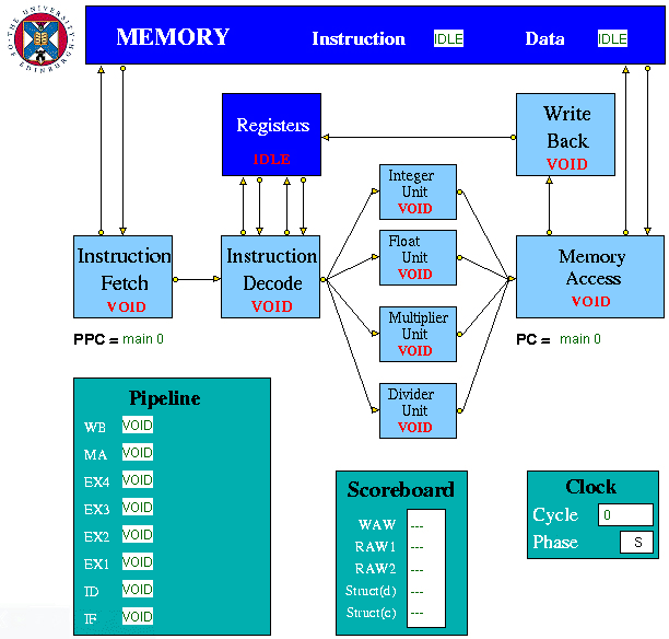
Figure 5. The HASE MIPS2 Model
| Instruction | Description | Example | Result |
| LB | Load Byte | LB R3 1(R0) | Loads Byte from memory location 1 |
| LBU | Load Byte Unsigned | LBU R4 1(R0) | Loads Byte Unsigned from memory location 1 |
| SB | Store Byte | SB R1 1(R0) | Stores Byte in R1 into memory location 1 |
| LH | Load Halfword | LH R4 2(R0) |
Loads Halfword from memory location 2 into R4 |
| LHU | Load Halfword Unsigned | LHU R4 2(R0) | Loads Halfword Unsigned from memory location 2 into R4 |
| LUI | Load Upper Immediate | LUI R1 124 | Load 124 in the upper half of regester R1 |
| SH | Store Halfword | SH R5 6(R0) | Stores Halfword from R5 into memory loction 6 |
| LW | Load Word | LW R4 8(R0) | Loads Word from data memory loaction word 8 into R4 |
| SW | Store Word | SW R3 16(R0) | Stores Word in R3 into location 16 in data memory |
| LWC1 | Load Word to an FPR | LWC1 F0 0(R0) | Loads Word from data memory location word 0 into F0 |
| SWC1 | Store Word from FPR | SWC1 F1 8(RO) | Stores Word in F1 into location 8 in data memory |
Table 2a. Load/Store Instructions
| Instruction | Description | Example | Result |
| ADDI | Add Immediate Word | ADDI R1 R2 -4 | Store R2 + -4 in R1 |
| ADDIU | Add Immediate Unsigned Word | ADDIU R1 R2 16 | Store R2 + 16 in R1 |
| ADD | Add Word | ADD R1 R2 R3 | Store R2 + R3 in R1 |
| ADDU | Add Word Unsigned | ADD R1 R2 R3 | Store R2 + R3 in R1 |
| MULT | Multiply integers | MULT R1 R2 | Store R1 x R2 in HI register |
| MULTU | Multiply unsigned integers | MULTU R3 R4 | Store R3 x R4 in HI register |
| DIV | Divide integers | DIV R1 R2 | Store R1 / R2 in HI register |
| DIVU | Divide unsigned integer | DIVU R3 R4 | Store R3 / R4 in HI register |
| SUB | Subtract Word | SUB R1 R2 R3 | Store R2 - R3 in R1 |
| SUBU | Subtract Word Unsigned | SUB R1 R2 R3 | Store R2 - R3 in R1 |
| SLT | Set on less than | SLT R1 R2 R3 | If R2 is less than R3 set R1 to be 1 else set it to 0 |
| SLTI | Set on less than Immediate | SLTI R1 R2 5 | If R2 is less than 5 then set R1 to 1 else set it to 0 |
| SLTU | Set on less than Unsigned | SLTU R1 R2 R3 | If the unsigned value of R2 is less than the unsigned value R3 set R1 to 1 else set it to 0 |
| SLTIU | Set on less than Immediate Unsigned | SLTIU R1 R2 6 | If the R2 is less than 6 (after sign extension)set R1 to 1 else set it to 0 |
Table 2b. Arithmetic Integer Instructions
| Instruction | Description | Example | Result |
| AND | And | AND R1 R2 R3 | Stores result of R2 AND R3 into R1 |
| ANDI | And Immediate | ANDI R1 R1 19 | Stores the result of R1 AND 19 back into R1 |
| OR | Or | OR R1 R2 R3 | Stores result of R2 OR R3 into R1 |
| ORI | Or Immediate | ORI R1 R1 128 | Stores the result of R1 OR 128 back into R1 |
| XOR | Exclusive Or | XOR R1 R2 R3 | Stores result of R2 XOR R3 into R1 |
| XORI | Exclusive Or Immediate | XORI R1 R1 64 | Stores the result of R1 OR 64 back into R1 |
| NOR | Nor | NOR R1 R2 R3 | Stores result of R2 NOR R3 into R1 |
| SSL | Shift Word Left Logical | SSL R1 R2 4 | Shift R2 4 bits to the left and store in R1 |
| SRL | Shift Word Right Logical | SRL R1 R2 2 | Shift R2 2 bits to the right and store in R1 |
| SRA | Shift Word Right Arithmetic | SRA R3 R4 2 | Arithmetically shift R4 2 bits right and store in R3 |
| SLLV | Shift Word Left Logical Variable | SLLV R1 R2 R3 | Shift R2 left by R3 bits and store in R1 |
| SRLV | Shift Word Right Logical Variable | SRLV R1 R2 R3 | Shift R2 right by R3 bits and store in R1 |
| SRAV | Shift Word Right Arithmetic Variable | SRAV R1 R2 R3 | Shift R2 right arithmetically by R3 bits and store in R1 |
Table 2c. Logical Instructions
| Instruction | Description | Example | Result |
| BC1F | Branch on FP condition code false | BC1F loop | Branch to label 'loop' if FP code is false |
| BC1T | Branch on FP condition code true | BCT1 loop | Branch to label 'loop' if FP code is true |
| J | Jump | J 8 | Jump to instruction 8 |
| JR | Jump Register | J R1 | Jump to the instruction number held in R1 |
Table 2d Jump Instructions
| Instruction | Description | Example | Result |
| BEQ | Branch on equal | BEQ R1 R2 4 | Branch forward 4 instructions if R1 and R2 are equal |
| BNE | Branch on not equal | BNE R1 R2 8 | Branch forward 8 instructions if R1 and R2 are not equal |
| BLEZ | Branch on less than or equal to zero | BLEZ R2 -2 | Branch back 2 instructions if R2 is less than or equal to zero |
| BGTZ | Branch on greater than zero | BGTZ R2 -2 | Branch back 2 instructions if R2 is greater than zero |
| BLTZ | Branch on less than zero | BLTZ R2 3 | Branch forward 3 instructions if R2 is less than zero |
| BGEZ | Branch on greater than or equal to zero | BGTZ R2 5 | Branch forward 5 instructions if R2 is greater than or equal to zero |
Table 2e Branch instructins
| Instruction | Description | Example | Result |
| Instruction | Description | Example | Result |
| BREAK | Breakpoint | BREAK | Halt |
| NOP | No Operation | NOP | No operation |
Table 2f. Other Instructions
Instruction Description Example Result
MFHI Copy the special purpose HI register to a GPR
MFHI R2 Copies the HI register to R2
MFLO Copy the special purpose LO register to a GPR MFLO R2
Copies the LO register to R2
MTHI Copy a GPR to the special purpose HI register MFHI R5
Copies R5 to the HI register
MTLO Copy a GPR to the special purpose LO register MFLO R5
Copies R5 to the LO register
MTC1 Copy a word from a GPR to a FPU register
MTC1 R3 F2
Copies R3 to F2
MFC1 Copy a word from a FPU register to a GPR
MFC1 R5 F3
Copies F3 to R5
MOVS Copy a word between FPU registers
MOVS F1 F2
Copies F2 to F1
Table 2g Move Instructions
| Instruction | Description | Example | Result |
| CVTWS | Convert a FP value to a 32-bit fixed-point value | CVTWS F0 F2 | The value in F2 is converted to a 32-bit word and stored in F0 |
| CVTSW | Convert a 32-bit fixed-point to a FP value | CVTSW F0 F1 | The value in F1 is converted to a FP value and stored in F0 |
Table 2h. Floating point Conversion Instructions
| Instruction | Description | Example | Result |
| ABSS | Compute absolute value of an FP value | ABSS F2 F3 | Store absolute value of F3 in F2 |
| ADDS | Add FP values | ADDS F1 F2 F3 | Store F2 + F3 in F1 |
| NEGS | Negate an FP value | NEGS F1 F2 | The negated value of F2 is stored in F1 |
| SUBS | Subtract FP values | SUB F1 F2 F3 | Store F2 - F3 in F1 |
| MULS | Multiply FP values | MULS F1 F2 F3 | Store F2 x F3 in F1 |
| DIVS | Divide FP values | DIVS F1 F2 F3 | Store F2 / F3 in F1 |
Table 2i Floating point Arithmetic Instructions
| Instruction | Description | Example | Result |
| CFS | Set FP condition code false | CFS R1 R2 | Sets FP condition code false |
| CEQS | Set FP condition code on equal | CEQS R2 R3 | Sets FP condition code true if R2 is equal to R3 else set it false |
| COLTS | Set FP condition code on less than | COLTS R3 R4 | Sets FP condition code true if R3 is less than R4 else set it false |
| COLES | Set FP condition code on less than or equal to | COLES R4 R5 | Sets FP condition code true if R4 is less than or equal to R5 else set it false |
Table 2j. Floating point Compare Instructions
 |
 |
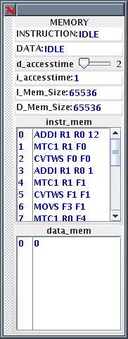
Figure 6. MiPS2 Memory and Registers Displays
The Hi-Lo Register is used to hold the result of MULT and DIV instructions with 64 bit accuracy. However this model simplifies the Hi-Lo registers using only the Hi register to return the result of a integer multiply or divide, for future development however the Lo register is also include in the model.
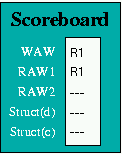
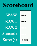
Figure 7(b) shows the Scoreboard display when the first of the following pair of instructions reaches the Integer Execution Unit:
LW R1 1(R0)
ADDI R1 R1 2
The first instruction loads R1 with a value accessed from memory, and until it completes, the second instruction, which increments R1, suffers both a WAW and a RAW hazard. In the following sequence:
LF F1 4(R0)
LF F2 5(R0)
ADDS F3 F1 F2
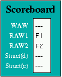
the third instruction requires the values which the previous two instructions load into F1 and F2, and when it reaches the Instruction Decode Unit, it suffers a RAW hazard on both its source operands, as illustrated in Figure 7(c).
 |
 |
 |
| (a) | (b) | (c) |
 |
 | |
| (d) | (e) |
Figure 7. Hazard Displays
To ensure that such situations are correctly handled, the Scoreboard maintains a Latency Pipeline. When an instruction is issued, its latency value is entered into the Latency Pipeline. As an instruction moves through the Execution Unit pipeline, its latency value moves through the Latency Pipeline, decremented by 1 at each move. Thus a multiply instruction has a latency of 3 when it is issued, but in the next clock its remaining latency is only 2.
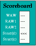
As latency values are moved through the Latency Pipeline in each clock period, the presence or absence of each possible latency value is recorded. If an instruction about to be issued to one of the execution units has the same latency value as an instruction already in the Latency Pipeline, it is held up for one clock period and then the check is performed again. Once there is no latency value in the Latency Pipeline equal to the new instruction’s latency value, it can be issued. The Scoreboard displays the existence of a Struct(d) hazard as shown in Figure 7(d).
A Branch cannot, in any case, be executed until all previous instructions have completed. Since a Branch instruction passing through the Integer Unit could overtake an instruction in the Multiply or Divide Units, a Branch must also be held up in the Instruction Decode Unit until there are no instructions in any of the Execution Units. This condition is monitored by the Scoreboard, which records the presence of any instruction with a latency value greater than zero in its Latency Pipeline, and displayed as a Struct(c) hazard as shown in Figure 7(e).
Clearly there are many alternative strategies for dealing with Branch instructions which could be modelled, and different HASE models will be developed over time. The current model shows the hold-ups ocurring in the Instruction Fetch and Instruction Decode Units and the values of PC and PPC changing.
| 0 | ADDI R1 R0 12 | R1 = R0 + 12 (=12) |
| 1 | MTC1 R1 F0 | F0 = R1 (copy R1 to F0) |
| 2 | CVTWS F0 F0 | F0 = F0 converted from 32-bit fixed point to a FP value (=12.0) |
| 3 | ADDI R1 R0 1 | R1 = R0 + 1 (=0) |
| 4 | MTC1 R1 F1 | F1 = R1 (copy R1 to F1) |
| 5 | CVTWS F1 F1 | F1 = F1 converted from 32-bit fixed point to a FP value (=1.0) |
| 6 | MOVS F3 F1 | F3 = F1 (copy F1 to F3) |
| 7 | MTC1 R0 F4 | F4 = R0 (copy R0 to F4) |
| 8 | CVTWS F4 F4 | F4 = F4 converted from 32-bit fixed point to a FP value (=0.0) |
| loop | Label (loop) - does not count as an instruction | |
| 9 | DIVS F2 F3 F0 | F2 = F3 / F0 |
| 10 | MULS F1 F1 F2 | F1 = F1 x F2 |
| 11 | SUBS F0 F0 F3 | F0 = F0 - F3 (decrement F0 by 1) |
| 12 | ADDS F1 F1 F3 | F1 = F1 + F3 (increment F1 by 1) |
| 13 | CEQS F0 F4 | If F0 = F4 (F0 = 0) set the FP condition code to true, else set it to false |
| 14 | BC1F loop | Branch to label loop if the condition code is false |
| 15 | NOP | No operation |
| 16 | SWC1 F1 0(R0) | Store the value in F1 to memory byte location 0 |
| 17 | BREAK | Halt the processor |
| 18 | NOP | No operation |
Return to Computer Architecture Simulation Models

HASE Project