Rigid ASSEMBLYs should meet both existence and identity requirements.
Most real objects are compact solids and one manifestation of this is connectedness of all object surfaces. Hence, surfaces composing the object must somehow be directly or transitively connected to each other without using unrelated surfaces.
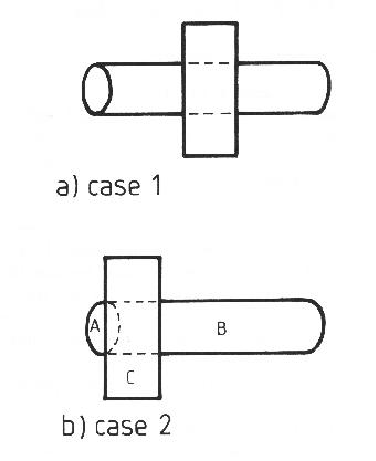
Unfortunately, it is difficult to always determine if two surfaces are directly or indirectly connected. Convex surface orientation discontinuity boundaries definitely mean connectedness, but concave boundaries are ambiguous regarding surface connectivity. Because of self-occlusion, direct connections may not be visible, as when one subcomponent overlaps another. Finally, obscuring objects can prevent observation of adjacency, though surface reconstruction (Chapter 4) eliminates some cases of this. Other cases, like that in Figure 10.3 are not solved by this.
Because of these difficulties, hypotheses will be rejected if it is certain that they cannot be fully connected, i.e., if there are subcomponents between which no connection exists. (Of course, two isolated objects could be connected by hidden structure to a common background, but here we assume objects are seen in general position.)
The implemented test is:
| Let: | |
| { |
|
 a) a) |
|
| b) there is a surface cluster with a front-side-obscuring or concave relation to both |
|
| If: | |
| for some |
|
| Then: | the hypothesis is incorrectly formed. |
This test rejects the false cube seen in Figure 10.1.
For rigid objects, the essence of identity is shape, and surface images make this information directly available. Given the surface image, the observed shape could be compared to that of each object from each viewpoint, but this approach is computationally infeasible. A more parsimonious solution follows, which also considers weak segmentation boundaries and occlusion.
Intuitively, correct object identification is assumed if all the right structures are found in the right places. Given the connectivity guaranteed by the above test, merely having the correct components is likely to be adequate, because the subcomponents of most objects only fit together rigidly and completely in one way (disregarding highly regular objects, like blocks). But, because there are likely to be a few counter-examples, especially with symmetric objects and misidentifications of similar surfaces, geometric, as well as topological, consistency is required. The requirement of consistent reference frames will eliminate many arbitrary groupings (and was demonstrated in the previous chapter).
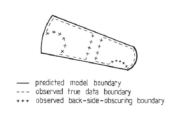
Surfaces that are connected according to the model should be connected in the scene. This does not always imply adjacency is observable, because object boundaries are not visible from all viewpoints.
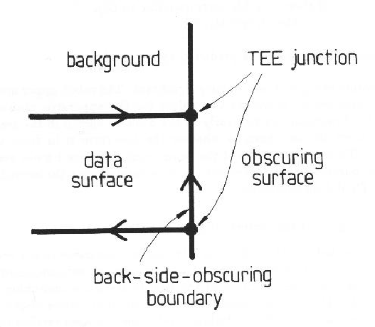
Occlusion affects verification because some surfaces may be partially or completely missing or a surface may be broken up by closer surfaces. Moreover, true surface boundaries may be obscured. The remaining true surface boundaries will be connected to back-side-obscuring boundaries in different locations. Since these are not model features, they are ignored.
Based on these ideas, the rigid object identity constraints are:
These constraints were implemented as the following tests:
| Let: | ||
| { |
||
| { |
||
| Then: | ||||
| For each |
||||
| For each corresponding |
||||
 |
( |
|||
 |
( |
|||
| Let: | ||||
| If: | ||||
| or | ||||
| Then: | the hypothesis is incorrectly formed | |||
Occlusion also has distinctive characteristics, and thus the hypothesis that an object is partially or fully obscured should be subject to some verification. Back-side-obscuring boundaries usually signal this occurrence, though not always. When a curved surface goes from facing the viewer to facing away, self-occlusion occurs without back-side-obscuring boundaries. When back-side-obscuring boundaries are present, though, three new constraints can be added:
Constraint ![]() was not applied because parameter estimation errors
made it difficult to check this condition reliably
(e.g. predicted model and data surfaces did not overlap adequately).
Constraint
was not applied because parameter estimation errors
made it difficult to check this condition reliably
(e.g. predicted model and data surfaces did not overlap adequately).
Constraint ![]() was guaranteed assuming image labeling was correct,
which was the case here.
was guaranteed assuming image labeling was correct,
which was the case here.
Because of parameter estimation errors, it is likely that there are self-occlusions predicted during raycasting that are not observed (because of surfaces becoming slightly obscured). Hence, the test of verifying predicted self-occlusions was not performed. While it is also possible for slightly obscured data surfaces to be predicted as not obscured, if a self-occlusion was significant enough to be observed, then prediction was likely to show it even with parameter estimation errors. Hence, only the reverse test was implemented:
| Let: | |
| { |
|
| { |
|
| { |
|
| front( |
|
| If: | |||
| For each | |||
| If there | is a |
||
| then front( |
|||
| Then: the self-occlusion is as predicted by the model. | |||
One application of ![]() was particularly significant.
The robot upper and lower arms are nearly symmetric, so there
are two values for the upperarm position and joint angle where
the lowerarm can be nearly in the position shown in the test scene.
The difference between the two cases is whether the lowerarm
is in front of or behind the upperarm.
Though the depths of the component reference frames are different in the
two cases, parameter tolerances did not completely reject the second alternative.
Happily, test
was particularly significant.
The robot upper and lower arms are nearly symmetric, so there
are two values for the upperarm position and joint angle where
the lowerarm can be nearly in the position shown in the test scene.
The difference between the two cases is whether the lowerarm
is in front of or behind the upperarm.
Though the depths of the component reference frames are different in the
two cases, parameter tolerances did not completely reject the second alternative.
Happily, test ![]() did discriminate.
did discriminate.