The process of rectification can be summarised as follows:
   function [T1,T2,Pn1,Pn2] = rectify(Po1,Po2)
   % RECTIFY compute  rectification  matrices
   %
   % [T1,T2,Pn1,Pn2] = rectify(Po1,Po2) computes the
   % rectifying projection matrices "Pn1", "Pn2", and
   % the rectifying transformation of the retinal plane
   % "T1", "T2" (in homogeneous coordinate). The arguments
   % are the  two old projection matrices "Po1" and "Po2".

   % focal lenght
   % (extp(a,b) is external product of vectors a,b)
   au = norm(extp(Po1(1,1:3)', Po1(3,1:3)'));
   av = norm(extp(Po1(2,1:3)', Po1(3,1:3)'));

   % optical centres
   c1 = - inv(Po1(:,1:3))*Po1(:,4);
   c2 = - inv(Po2(:,1:3))*Po2(:,4);

   % retinal planes
   fl = Po1(3,1:3)';
   fr = Po2(3,1:3)';

   nn = extp(fl,fr);

   % solve the four systems
   A = [ [c1' 1]' [c2' 1]' [nn'  0]' ]';
   [U,S,V] = svd(A);
   r = 1/(norm(V([1 2 3],4)));
   a3 = r * V(:,4);
   A = [ [c1' 1]' [c2' 1]' [a3(1:3)' 0]' ]';
   [U,S,V] = svd(A);
   r = norm(av)/(norm(V([1 2 3],4)));
   a2 = r * V(:,4);
   A = [ [c1' 1]' [a2(1:3)' 0]' [a3(1:3)' 0]' ]';
   [U,S,V] = svd(A);
   r = norm(au)/(norm(V([1 2 3],4)));
   a1 = r * V(:,4);
   A = [ [c2' 1]' [a2(1:3)' 0]' [a3(1:3)' 0]' ]';
   [U,S,V] = svd(A);
   r = norm(au)/(norm(V([1 2 3],4)));
   b1 = r * V(:,4);

   % adjustment
   H = [
     1 0 0
     0 1 0
     0 0 1 ];

   % rectifying  projection matrices
   Pn1 = H * [ a1 a2 a3 ]';
   Pn2 = H * [ b1 a2 a3 ]';

   % rectifying image transformation
   T1 = Pn1(1:3,1:3)* inv(Po1(1:3,1:3));
   T2 = Pn2(1:3,1:3)* inv(Po2(1:3,1:3));
Notice that, owing to a sign ambiguity in the computation of
eigenvalues, the rectified images can experience a reflection along
the vertical or horizontal axis. This can be detected by checking
whether or not the ordering between the two diagonal corners of the
image is preserved. If a reflection occurs, it can be trivially
compensated by pre-multiplying both rectifying PPM by a matrix
![]() of the form:
of the form:

with ![]() .
.
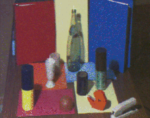
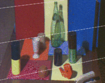
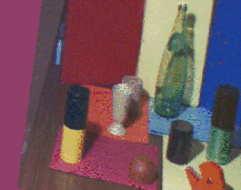
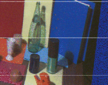
Figure 5 is another example of rectification of a generic stereo pair.
 |
 |
 |
 |
The MATLAB code of function rectify and the implementation in C of the image rectification algorithm can be found on line.