 at a particular point, and recover the surface shape along a strip extending from that point. Provided we know p and q at the given point, then as we extend our solution from
  to
to  the changes in p and q can be computed by


As in the previous case, we assume that we have the coordinates  at a particular point, and recover the surface shape along a strip extending from that point. Provided we know p and q at the given point, then as we extend our solution from
  to
to  the changes in p and q can be computed by


where  i.e.
i.e.  ,
,
 and
and  .
.

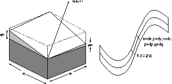
Figure 7: Differential surface geometry and the characteristic strip
This can be written more compactly as

The Hessian provides information on surface curvature; the trace of the Hessian is the Laplacian of the depth, which is twice the mean curvature (discussed elsewhere).
Next, we recall the image irradiance equation 4. Differentiate each side of  with respect to x using the chain rule,

Similarly, differentiate with respect to y,

or, using the Hessian matrix,

Now, we have a relationship between the image gradient  and
the gradient in the reflectance map
  . Equations 35 and
36 have three unknowns
  and
and  . In general this cannot be solved. However, we can continue the solution in a specific direction, as we did in the linear case. Let

From Equations 34 and 38.

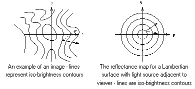
where  is a small quantity. Examining Figure 8, as we extend the strip, so we move to a new point in
  and
and  spaces. The change in
  can be computed provided the step taken in image space,
  , shown by the dotted arrow is parallel to the direction of steepest descent in gradient space,
  shown by the solid arrow. In turn, the direction of change in gradient space (dotted) arrow is parallel to the image gradient (solid arrow).

Figure 8: A small movement in image and gradient space

As in the linear case, we require starting values for the strips; these may be occluding contours, or more strictly parts of the surface adjacent to the occluding contours, or alternatively the ``singular points'' which correspond to maxima in the reflectance map.
Start the solution at a known pointREPEAT Take a small step
along a characteristic strip
from
to
. This is parallel to the direction of steepest ascent or descent in the reflectance map ( the dotted arrow in
space) Compute changes in p and q from the changes in
Define new values for p and q Compute new values for R,
and
Compute the new value for z Reset start point to new value of
UNTIL ( a discontinuity is reached in the image function)
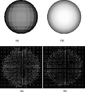
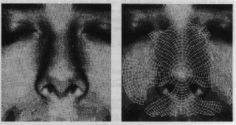
As an illustration of the method, Figure 9 shows needle diagrams of simple spheres, computed from the shading pattern and the extremal contour which surrounds the sphere's surface. In fact this result was obtained by a minimisation method, but it serevs as an illustration. The difference between the two pictures is in the raytracer; the one on the left uses a more crudely factetted approximation and the needle map is further for a true sphere. Another illustration is given in Figure 10 from [Horn, 1986]. This uses the tip of the nose, or more accurately a quasi-circular strip surrounding the nose as the set of starting points for the growth of the characteristic strips. The result is a relief map of part of the face.

Figure 9: Building the surface normal map of a sphere

Figure 10: Building the shape of the face from characteristic strips


[ A special case: the linear reflectance map |
References ]
Comments to: Sarah Price at ICBL.