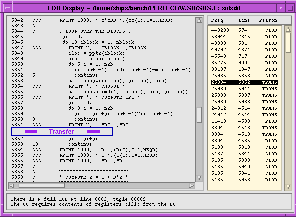
Figure 13: An LOD from DYFSEM which can be propagated to the enclosing loop nest by improved decoupling (click on image to view at full scale)
Figure 13 below illustrates where improvements to the decoupling
algorithm could be applied. The computation of YR at the LOD
point is occuring on the CU, but as there is no reaching use of
YR within the enclosing loop (except the use of YR
within that scalar recurrence) the CU need not compute YR.
However, as it is needed on the CU later on in that routine, the
decoupling algorithm determines that the CU should compute it, and
this causes a transfer from the DU. If the transfer is delayed
until after the enclosing loop has completed, then the frequency
of transfers (and hence LODs) will be minimized.

Figure 13: An LOD from DYFSEM which can be propagated to the
enclosing loop nest by improved decoupling (click on image to view at full scale)