The goal of the surface cluster formation process is to isolate the visible portion of each distinct three dimensional object's surface, so that later stages of the scene analysis can associate a model with the surface cluster.
The primary input into the process is the set of surface hypotheses produced as output of the processes described in Chapter 4. The surface hypotheses are linked by adjacency, and relative surface orientation at the boundaries is known.
The output of the process is a set of surface clusters hierarchically linked by inclusion, with each consisting of a set of surface patches. Though the surface cluster is not closed (i.e. it is missing the back side), it defines a solid bounded in front by the visible surfaces.
The surface cluster formation process is closely linked to the model structure known as the ASSEMBLY, which is defined in Chapter 7. The ASSEMBLY is a model of a three dimensional solid and is composed of SURFACEs or recursively defined subcomponents. Properties we would like the surface cluster formation process to have are:
The process of creating the surface clusters has three steps:
The algorithm is conservative, in that it
tries to avoid splitting the smallest model ASSEMBLYs between
surface clusters at the price of creating clusters containing several
ASSEMBLYs.
Splitting an object between several different surface clusters would be
catastrophic because it asserts that the segregated components are unrelated.
Creating clusters larger than single objects is mainly an annoyance, because
the rest of the recognition process then has more work to identify the objects.
Determining Surface Connectivity
The segmented surface image can be thought of as a graph, where the nodes of the graph represent the surface patches and the arcs of the graph represent surface adjacency. These arcs will be labeled as connecting or segmenting, according to criteria based on boundary type and configuration. The connection criteria are simple and logical, except for a laminar surface case (described shortly) and are based on obvious three dimensional properties of surface connectivity and object depth ordering. Splitting the graph at segmenting boundaries partitions the scene into sets of connected surfaces - forming the primitive surface clusters.
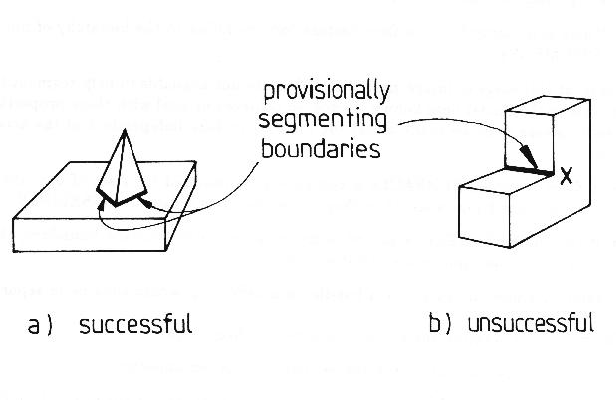
We assume that the modeled objects are segmented into subcomponents at chains of connected concave boundaries. As concave model boundaries are observed as concave image boundaries, the latter are potentially segmenting. In Figure 5.1 part (a), the concave boundary is truly segmenting.
Further, distinct objects are often on opposite sides of concave surface orientation boundaries. For example, a block sitting on a table has concave boundaries isolating it from the table. Nameable subcomponents of natural objects often fit flushly with concave boundaries, as in the nose-to-face junction. Because the boundary is concave, it is indeterminate whether the two surfaces are joined or merely in contact. Moreover, it is usually impossible to tell which surface passes underneath the other past the point of the observed concave boundary. So, the conservative approach suggests that this boundary causes a segmenting arc. Assuming concave boundaries necessarily imply segmentation leads to contradictions as seen in Figure 5.1 part (b), where there is no reasonable shape boundary at point X to continue segmentation. If there are other connections between the two surfaces that do not involve a segmenting boundary, then the final surface cluster will include both surfaces.
A more complicated case occurs with crack-type boundaries. Here, two surfaces may be coincidentally aligned, or part of a flush contact boundary (as often occurs with revolute joints). Because of the ambiguity, it is assumed that connectivity does not hold across crack-type joints.
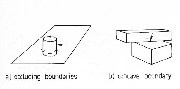
Whenever one object sits in front of or on top of another, the intervening boundary is always either concave or obscuring, as illustrated in Figure 5.2. To complete the isolation of the cylinder in part (a) from the background plane, a rule is needed to handle obscuring boundaries. As these usually give no clues to the relation between opposing surfaces (other than being depth separated), surfaces will usually be segmented across these, and so segmenting arcs join the nodes representing these surfaces.
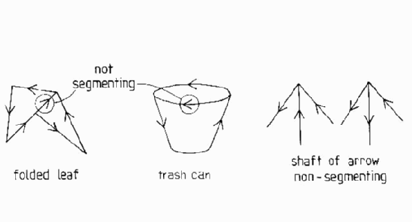
Connectivity holds across some obscuring boundaries. Disregarding coincidental alignments, the one exception found occurs when laminar objects fold back on themselves, as illustrated in Figure 5.3. This figure shows a leaf folded over and the two surfaces of a trash can. The arrows on the boundary mean that it is an obscuring type boundary with (here) the front surface lying to the left when looking along the boundary in the direction of the arrow. In both cases, the two surfaces are connected, even though an obscuring boundary intervenes, and so here a connecting arc is used. Fortunately, this case has a distinctive signature: the arrow vertices shown at the right side of the figure are paradigmatic of the junction formed by a folding laminar surface. Viewpoint analysis (by octant) shows that these are the only special trihedral vertex label cases needed for two connected laminar surfaces. Curved laminar surfaces are (here) treated locally as two connecting planar laminar surfaces.
Two surfaces lying on opposite sides of convex boundaries ordinarily belong to the same object, though coincidental alignment may also produce this effect. Hence, surfaces on opposite sides of convex boundaries cause connecting arcs. A surface orientation boundary that is both concave and convex in places is broken up by the curve segmentation assumptions. To summarize, the constraints that specify the connectivity of surface patches are:
Forming Primitive Surface Clusters
Primitive surface clusters are formed by collecting all surface patch nodes
that are directly or transitively connected in the graph, once all
arcs are labeled as "segmenting" or "connecting".
Thus, image features that can only belong to the same object lie in the same
surface cluster, and features that possibly belong to other objects do not
lie in the cluster.
Depth Merged Surface Clusters
The goal of the surface cluster process is to associate all components of an object in some surface cluster. All components of a model may not occur in the same primitive surface cluster for several reasons:
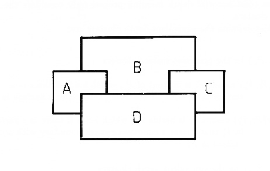
This merging process is constrained by the following observation, referring to Figure 5.4. If there are four surface clusters (A, B, C, and D), an object might be wholly contained in only one of these, but it might also obscure itself and be in more than one. Hence, reasonable groupings of surface clusters containing whole objects are AB, AD, BC, BD, CD, ABC, ABD, ACD, BCD and ABCD. AC is an unlikely grouping because there is no obvious relation between them.
Merging all surfaces behind a given surface does not solve the problem. If only surfaces ABC were present in the above scene, then merging behind does not produce a containing surface cluster if the true object was ABC. Similarly, the technique of merging all surfaces in front fails if both the object and grouping were ACD. Neither of these processes individually produce the correct clusters. To avoid this problem, a more combinatorial solution was adopted.
Before the computational constraints for depth merging are given, one refinement is necessary. Rather than considering depth merging for all surface clusters, certain sets of surface clusters can be initially grouped into equivalent depth surface clusters. These occur when either surface clusters mutually obscure each other, or when there is no obvious depth relationship (e.g. they lie across a concave surface boundary). An example of where two surface clusters mutually obscure is with the robot lower arm and trash can surface clusters in the test image. When these cases occur, all such primitive surface clusters can be merged into a single equivalent depth surface cluster. Thereafter, the combinatorial depth merging process only considers the equivalent depth surface clusters.
The properties defining the equivalent depth clusters are:
Let:
| { |
be the primitive surface clusters |
| front( |
means |
| surface in |
|
| beside( |
means |
| in |
|
| { |
be the equivalent depth clusters |
| = {
|
|
Then, the relationship between the ![]() and the
and the ![]() is defined by:
is defined by:
| (1) If |
||
| front( |
||
| or | ||
| beside( |
||
| (2) If |
||
| not front( |
||
| and | ||
| not beside( |
||
| (3) The |
||
Equivalent depth surface clusters that only contain a single primitive surface cluster are replaced by that primitive surface cluster (for compactness).
Then, using the same definitions, the depth merged surface clusters are sets of equivalent depth surface clusters:
| Let: | ||
| efront( |
mean equivalent depth surface cluster |
|
| equivalent depth surface cluster |
||
| primitive surface clusters |
||
| linked( |
holds if efront( |
|
| { |
||
| Then: | ||
| the |
||
| there is a |
||
The implementation of these definitions is straightforward and leads first to the construction of primitive surface clusters, then to formation of equivalent depth clusters and finally to the linking of these into larger depth merged surface clusters. The background and picture frame surfaces are omitted.
The surface clusters are linked into the image description graph started in Chapter 3 by the following additions: