
We have developed a camera calibration process that estimates the intrinsic parameters of a camera, including the radial and tangential lens distortion parameters. There are 2 novel contributions:
This research is based on calibration charts from which the center-of-mass of the features is the calibration point. Many people use checkerboard grids. It is our opinion that the circular feature grids are better, because estimating the corner points on the checkerboard grids can be done to 0.1 pixel accuracy, whereas estimating the center of a circular feature can be done to 0.01 pixel accuracy.
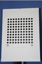
This webpage explains how we calibrate a
camera using a planar calibration chart. The chart we use for calibration
looks something like this:
The chart is made by attaching a laser-printed paper to a planar surface. The circles on the paper provide known positions in 3D. When a camera looks at this chart from a few different angles, the camera's intrinsic and extrinsic paramters can be calculated from the image observations. The idea of calibrating a camera using a mono-plane chart has been explored by several reseachers [1-3] and the theories have been well laid out. Here, what we improve is the practice. We solve two problems: 1) how to accurately extract the projected circles from images of the calibration chart; 2) how to compensate for the printing shift of the circles on the calibration chart.
|
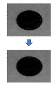 |
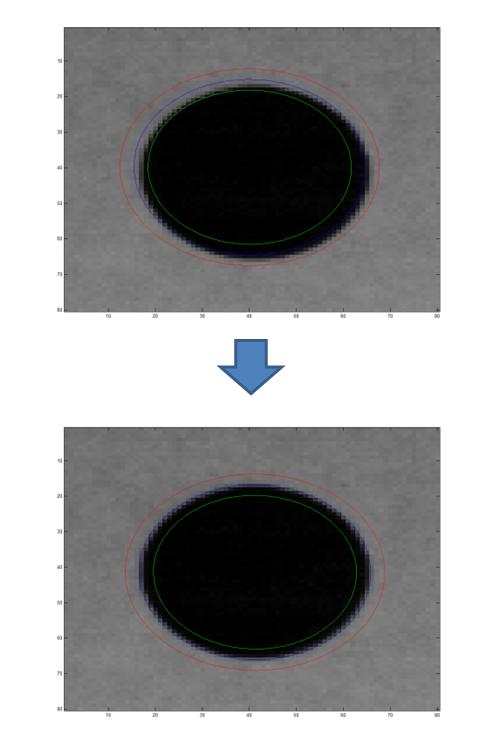
( Click to enlarge. The blue line is the fitted ellipse.)
The process starts from a rough estimate of the
position, orientation and shape parameters (semi-axes) of the ellipse.
It calculates the mean values of the intensities in the outer and inner
belt areas of the ellipse. A belt is the area between the ellipse and
another concentric ellipse (that shares the same center, eccentricity
and orientation). As illustrated above, the blue curve is the ellipse,
the area between the red and blue curves is its outer belt and the area
between the green and blue curves is its inner belt. The ellipse that
maximizes the difference between the mean intensity values of the two belts is
considered to be the optimal ellipse that can be estimated from the
image data. For more technical description of the method, please refer
to our paper.
The matlab code is here.
One question about applying this method is the initialization of the ellipse. For this, we first extract the black dots (illustrated in the above figures) using blob detection techniques and use the centroids of the black dots as the first estimate of the ellipse centers to calibrate the camera. We do not require an accurate extraction of the black dots at this stage. The estimate of the dot centroids can have a few pixels error. The next step is then to project the circles on the calibration chart back to the image plane and get a coarse estimate of the positions, orientations and shape parameters of the corresponding ellipses. The estimated ellipse parameters are used to initialize the optimization to maximize the inside and outside intensity difference for each single ellipse.
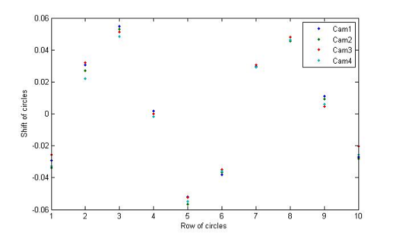
In the matlab code, we provide a function: dy = find_shift_m() to calculate the shifts of the circles on the calibration chart using the four cameras. The calibration data files contained in the code were produced by using the ellipse extraction method described above.
This work was done in the ChiRoPing project, funded by the EC's IST programme, STREP project 215370, in the ICT Challenge 2: "Cognitive Systems, Interaction, Robotics".
We are grateful to the authors at Oulu university who provide camera calibration matlab functions used in this research .
Back to Edinburgh's ChiRoPing results page
