


The two main features of electromagnetic waves that are most commonly used in computer vision systems are the intensity and wavelength (interpreted as brightness and colour). However a third important feature that can be exploited is that of the polarisation of light. The polarisation is affected by various factors in a scene, such as surface shape, surface curvature, surface materials and the position of objects with respect to lightsources, and can therefore provide useful information about those objects [1]. In particular, polarisation imaging is useful for the determination of shape of specular (i.e. smooth and shiny) and transparent objects, where intensity and wavelength are less well defined for the object (for example a transparent object will take on the colour of whatever is behind it).
The theory behind polarisation imaging relies on two basic assumptions about the observed scene [2]. The first of these is that the scene is illuminated with completely unpolarised light. This means that any polarisation detected can be assumed to be purely down to reflection from the object. The second is that the object under scrutiny has a smooth reflective surface. This is to simplify the analysis so that the geometry of specular reflection can be used (i.e. that scattering is not a factor). Light reflected from the surface of the object becomes partially linearly polarised so that the extent to which it is polarised and the direction of polarisation is altered. It is differences in these two properties induced by the shapes of objects that are analysed in polarisation imaging.
By some consideration of the physics of electromagnetic waves it is possible to derive [3] the following equation for the degree of polarisation, ρ, of light reflected from a specular object:
Where n is the refractive index of the acrylic objects and θ the angle between the reflected (or incident) beam and the normal to the surface (shown in figure 1). ρ here ranges from 0 to 1 with 0 being totally randomly polarised, and 1 being totally linearly polarised.
Figure 1 Angle of normal with respect to incident/refelcted light ray [3]
By measuring the degree of polarisation of light incident on a camera, the above formula can be used to find the direction of the normal to the surface of the object. Having found the normal at a sufficient number of points [2], [3] on the object's surface it is then possible make a reconstruction of the surface.
In order to extract information from polarisation it is necessary to use stereo images of light of different polarisation. These are obtained with cameras recording the scene from behind polaroid filters at different relative orientations (hence passing light at different polarisations). If there is more light of a certain polarisation incident on one part of the image, this will show up as a brighter patch in image where that polarisation is not being filtered out. To get a measure of the difference the sum and difference signals are calculated [1]:
Where I(parallel) and I(perp) are the intensities of the light at orthogonal polarisations.
For an ideal linear polariser the image recreated by the PS signal should be equivalent to the conventional intensity image. The PD image however will contain areas of differing strength of signal as according to the polarisation of light in those areas. These differences in the strength of signal can then be used to extract features of the scene.
An example of the successful use of polarisation imaging in practice is given in [3], and in simulation as well as experiment in [2]. In [3] the 3-D surfaces of transparent, specular acrylic objects were mapped. Figure 2 shows their experimental setup.
Figure 2 Experimental Setup [3]
In [3] a camera was set up behind a polaroid filter above a variety of different transparent acrylic objects illuminated from all directions through a spherical diffuser. The diffuser ensured that all light incident on the objects was randomly polarised (i.e. had no dominant direction of polarisation). The camera then recorded an image, the polaroid filter was rotated, and the camera recorded a second image.
What was recorded by the camera was a pattern of light that had been polarised by reflection off the acrylic object. The degree to which it was polarised was measured and the surface normals over the object calculated using the above formula. An example of results obtained are shown in figure 3.
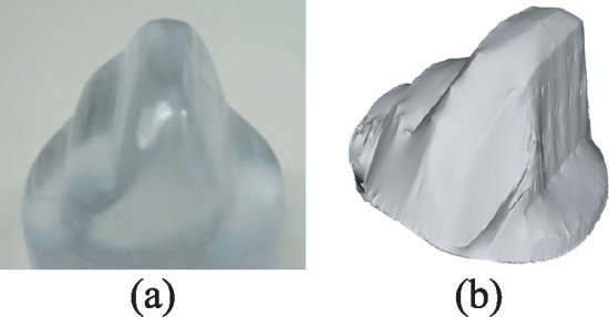
Figure 3 (a) Photograph of acrylic object. (b) Estimated shape. [3]
[1] Konstantin M. Yemelyanova, Shih-Schön Lina, William Q. Luisa, Edward N. Pugh, Jr. b, and Nader Enghetac, "Bio-inspired display of polarization information using selected visual cues", Proceedings of SPIE Vol. 5158 Polarization Science and Remote Sensing, 2003
[2] Stefan Rahmann and Nikos Canterakis, "Reconstruction of Specular Surfaces using Polarization Imaging" CVPR'01, IEEE Computer Society Conference on Computer Vision and Pattern Recognition, Hawaii, USA ,volume I, pages 149-155, IEEE Computer Society Press, December 2001.
[3] Daisuke Miyazaki, Masataka Kagesaway and Katsushi Ikeuchi, "Polarization-based Transparent Surface Modeling from Two Views" Proceedings of the Ninth IEEE International Conference on Computer Vision, 2003
[4] Daisuke Miyazaki, Robby T. Tan, Kenji Haray and Katsushi Ikeuchi "Polarization-based Inverse Rendering from a Single View" Proceedings of the Ninth IEEE International Conference on Computer Vision, 2003
[5] Stefan Rahmann "Reconstruction of Quadrics from Two Polarization Views" Iberian Conference on Pattern Recognition and Image Analysis (IbPRIA), Springer, LNCS 2652, pages 810-820, Mallorca, Spain, June 2003