

Next: Summary
Up: Defocus Blur of a
Previous: Analysis of Defocus Blur
For our numerical experiments we set c=1 meter, used the hyperboloid
mirror with k=4, and assumed the radius of the lens to be
5 centimeters. Initially, we just considered the point  on the mirror and set the distance from the
viewpoint to the world point
  to be l=5 meters.
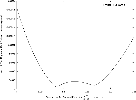
In Figure 10 we plot the area of the blur region
(on the ordinate) against the distance to the focused plane v
(on the abscissa). The smaller the area of the blur region,
the better focused the image will be. We see from
Figure 10 that the area never reaches exactly 0, and
so an image formed using this catadioptric sensor can never be
perfectly focused.
However, note that the minimum area is very
small, and in practice there is no problem focusing the image
for a single world point. Moreover, is is possible to use
additional corrective lenses to compensate for most of this
effect [Hecht and Zajac, 1974].
Figure 10:
The area of the blur region plotted against
the distance to the focused plane  for a
point
  on the hyperboloid mirror with k=4. In this
example, we have c=1 meter, the radius of the lens 5 centimeters,
and the distance from the viewpoint to the world point
l=5 meters. So,
  .The area never becomes exactly 0 and so the image can
never be perfectly focused. However, the area does become very
small and so focusing on a single point is not a problem in practice.
There are two
minima in the area which correspond to the two different foldings
of the blur region illustrated in Figures 11.
Also note that the distance at which the image will be best focused
(1.05-1.2 meters) is much less than the distance from the pinhole
to the world point (approximately 1 meter from the pinhole to the
mirror plus 5 meters from the mirror to the world point.) The
reason is that the mirror is convex and so tends to increase the
divergence of rays of light coming from the world point
 .
.
 |
Also note that the distance at which the image of
the world point will be best focused (i.e. somewhere in the range
1.05-1.2 meters) is much less than the distance from the pinhole
to the world point (approximately 1 meter from the pinhole to the
mirror plus 5 meters from the mirror to the world point). The reason
for this effect is that the mirror is convex. Hence, it tends to
increase the divergence of rays coming from the world point. For
the rays to converge and focus the image, a larger distance to
the image plane u is needed. A larger value of u corresponds
to a smaller value of v, the distance to the focused plane.
Next, we provide an explanation of the fact that there are
two minima of the blur area in Figure 10. As mentioned
before, for an isolated
conventional lens the blur region is a circle. In this case,
as the focus setting is
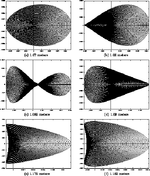
Figure 11:
The variation in the shape of the blur
region as the distance to the focused plane is varied. All of the
blur regions in this figure are relatively well focused. Note
that the scale of the 6 figures are all different and that
the scale on the two axes is, in general, different.
 |
adjusted to focus the lens, all points on the blur circle
move towards the center of the blur circle at a rate which is
proportional to their distance from the center of the blur circle.
Hence, the blur circle steadily shrinks until the blur region has
area and the lens
is perfectly focused. If the focus setting is moved further in the
same direction, the blur circle grows again as all the points on it move
away from the center. For a catadioptric sensor using a curved mirror,
the speed with which points move is dependent on their position in a
more complex way. Moreover, the direction in which the points are
moving is not constant. This behavior is illustrated in
Figures 11(a)-(f).
In Figure 11(a) the focused plane is 1.07 meters
from the pinhole and the image is quite defocused. As the focused
plane moves to 1.08 meters away in Figure 11(b),
the points in the left half of Figure 11(a) are moving
upwards more rapidly than those in the right half (the points in the
right half are also moving upwards.) Further, the points in the left
half are moving upwards more rapidly than they are moving towards the
right. This effect continues in Figures 11(c) and
(d). In Figure 11(d) all the points are still moving
horizontally towards the center of the blur region, but vertically
they are now moving away from the center. The points continue to move
horizontally towards the center of the blur region, but with those in
the left half again moving faster. This causes the blur region to overlap
itself as seen in Figure 11(e). Finally, for the
focused plane at 1.185 meters in Figure 11(f), all
points are moving away from the center of the blur region in both
directions. The blur region is expanding and the image becoming
more defocused.
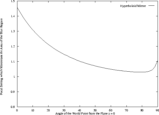
Figure 12:
The focus setting which minimizes the
area of the blur region in Figure 10 plotted against
the angle  which the world point
  makes with
the plane z = 0. We see that the
best focus setting for
  varies considerably
across the mirror from around 1.45 meters at the periphery of
the mirror
  , to only about 1.05 meters at
its center
  . In practice, these results
mean that it is very difficult to focus the entire scene at the
same time, unless additional compensating lenses are used
to compensate for the field curvature [Hecht and Zajac, 1974].
 |
Finally, we investigated how the focus setting which minimizes the
area of the blur region (see Figure 10) changes with
the angle  which the world point
  makes with
the plane z = 0. The results are displayed in Figure 12.
As before, we set c=1 meter, used the hyperboloid mirror with k=4,
assumed the radius of the lens to be 5 centimeters, and fixed
the world point
  to be l=5 meters from the effective
viewpoint
  . We see that the
best focus setting for
  varies considerably
across the mirror from around 1.45 meters at the periphery of
the mirror
  where the curvature is the
least, to only about 1.05 meters at its center
  where the curvature is the greatest. In practice,
these results, often referred to as ``field curvature''
[Hecht and Zajac, 1974], mean that it is very difficult to focus
the entire scene at the same time. Either the center of the mirror
is well focused or the points around the periphery are well focused.
Fortunately, it is possible to introduce additional
lenses which compensate for the field curvature caused by the
curved mirror [Hecht and Zajac, 1974].


Next: Summary
Up: Defocus Blur of a
Previous: Analysis of Defocus Blur
Simon Baker
1/22/1998


![]() which the world point
which the world point ![]() makes with
the plane z = 0. The results are displayed in Figure 12.
As before, we set c=1 meter, used the hyperboloid mirror with k=4,
assumed the radius of the lens to be 5 centimeters, and fixed
the world point
makes with
the plane z = 0. The results are displayed in Figure 12.
As before, we set c=1 meter, used the hyperboloid mirror with k=4,
assumed the radius of the lens to be 5 centimeters, and fixed
the world point ![]() to be l=5 meters from the effective
viewpoint
to be l=5 meters from the effective
viewpoint ![]() . We see that the
best focus setting for
. We see that the
best focus setting for ![]() varies considerably
across the mirror from around 1.45 meters at the periphery of
the mirror
varies considerably
across the mirror from around 1.45 meters at the periphery of
the mirror ![]() where the curvature is the
least, to only about 1.05 meters at its center
where the curvature is the
least, to only about 1.05 meters at its center ![]() where the curvature is the greatest. In practice,
these results, often referred to as ``field curvature''
[Hecht and Zajac, 1974], mean that it is very difficult to focus
the entire scene at the same time. Either the center of the mirror
is well focused or the points around the periphery are well focused.
Fortunately, it is possible to introduce additional
lenses which compensate for the field curvature caused by the
curved mirror [Hecht and Zajac, 1974].
where the curvature is the greatest. In practice,
these results, often referred to as ``field curvature''
[Hecht and Zajac, 1974], mean that it is very difficult to focus
the entire scene at the same time. Either the center of the mirror
is well focused or the points around the periphery are well focused.
Fortunately, it is possible to introduce additional
lenses which compensate for the field curvature caused by the
curved mirror [Hecht and Zajac, 1974].