Dilation is one of the two basic operators in the area of mathematical morphology, the other being erosion. It is typically applied to binary images, but there are versions that work on grayscale images. The basic effect of the operator on a binary image is to gradually enlarge the boundaries of regions of foreground pixels (i.e. white pixels, typically). Thus areas of foreground pixels grow in size while holes within those regions become smaller.
Useful background to this description is given in the mathematical morphology section of the Glossary.
The dilation operator takes two pieces of data as inputs. The first is the image which is to be dilated. The second is a (usually small) set of coordinate points known as a structuring element (also known as a kernel). It is this structuring element that determines the precise effect of the dilation on the input image.
The mathematical definition of dilation for binary images is as follows:
Suppose that X is the set of Euclidean coordinates corresponding to the input binary image, and that K is the set of coordinates for the structuring element.Let Kx denote the translation of K so that its origin is at x.
Then the dilation of X by K is simply the set of all points x such that the intersection of Kx with X is non-empty.
The mathematical definition of grayscale dilation is identical except for the way in which the set of coordinates associated with the input image is derived. In addition, these coordinates are 3-D rather than 2-D.
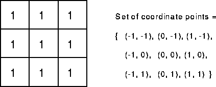
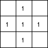
As an example of binary dilation, suppose that the structuring element is a 3×3 square, with the origin at its center, as shown in Figure 1. Note that in this and subsequent diagrams, foreground pixels are represented by 1's and background pixels by 0's.
Figure 1 A 3×3 square structuring element
To compute the dilation of a binary input image by this structuring element, we consider each of the background pixels in the input image in turn. For each background pixel (which we will call the input pixel) we superimpose the structuring element on top of the input image so that the origin of the structuring element coincides with the input pixel position. If at least one pixel in the structuring element coincides with a foreground pixel in the image underneath, then the input pixel is set to the foreground value. If all the corresponding pixels in the image are background, however, the input pixel is left at the background value.
For our example 3×3 structuring element, the effect of this operation is to set to the foreground color any background pixels that have a neighboring foreground pixel (assuming 8-connectedness). Such pixels must lie at the edges of white regions, and so the practical upshot is that foreground regions grow (and holes inside a region shrink).
Dilation is the dual of erosion i.e. dilating foreground pixels is equivalent to eroding the background pixels.
Most implementations of this operator expect the input image to be binary, usually with foreground pixels at pixel value 255, and background pixels at pixel value 0. Such an image can often be produced from a grayscale image using thresholding. It is important to check that the polarity of the input image is set up correctly for the dilation implementation being used.
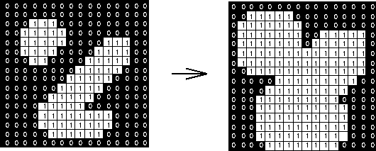
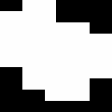
The structuring element may have to be supplied as a small binary image, or in a special matrix format, or it may simply be hardwired into the implementation, and not require specifying at all. In this latter case, a 3×3 square structuring element is normally assumed which gives the expansion effect described above. The effect of a dilation using this structuring element on a binary image is shown in Figure 2.
Figure 2 Effect of dilation using a 3×3 square structuring element
The 3×3 square is probably the most common structuring element used in dilation operations, but others can be used. A larger structuring element produces a more extreme dilation effect, although usually very similar effects can be achieved by repeated dilations using a smaller but similarly shaped structuring element. With larger structuring elements, it is quite common to use an approximately disk shaped structuring element, as opposed to a square one.
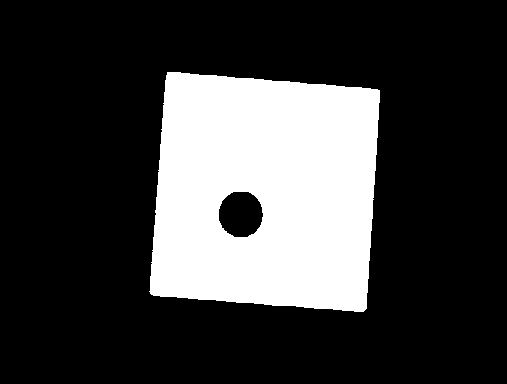
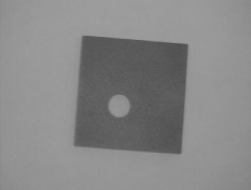
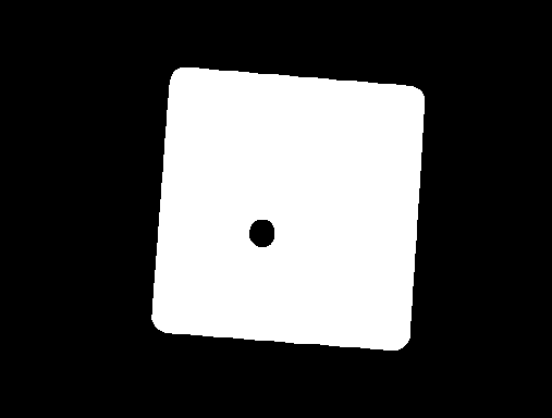
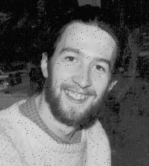
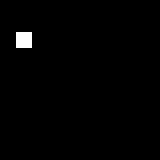
The image
shows a thresholded image of
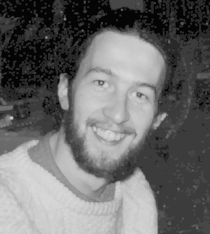
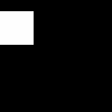
The basic effect of dilation on the binary is illustrated in
This image was produced by two dilation passes using a disk shaped structuring element of 11 pixels radius. Note that the corners have been rounded off. In general, when dilating by a disk shaped structuring element, convex boundaries will become rounded, and concave boundaries will be preserved as they are.
Dilations can be made directional by using less symmetrical structuring elements. e.g. a structuring element that is 10 pixels wide and 1 pixel high will dilate in a horizontal direction only. Similarly, a 3×3 square structuring element with the origin in the middle of the top row rather than the center, will dilate the bottom of a region more strongly than the top.
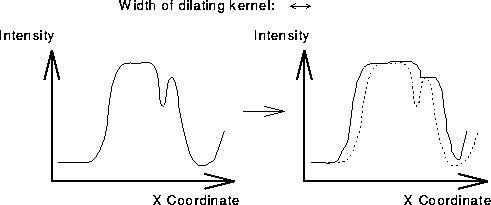
Grayscale dilation with a flat disk shaped structuring element will generally brighten the image. Bright regions surrounded by dark regions grow in size, and dark regions surrounded by bright regions shrink in size. Small dark spots in images will disappear as they are `filled in' to the surrounding intensity value. Small bright spots will become larger spots. The effect is most marked at places in the image where the intensity changes rapidly and regions of fairly uniform intensity will be largely unchanged except at their edges. Figure 3 shows a vertical cross-section through a graylevel image and the effect of dilation using a disk shaped structuring element.
Figure 3 Graylevel dilation using a disk shaped structuring element. The graphs show a vertical cross-section through a graylevel image.
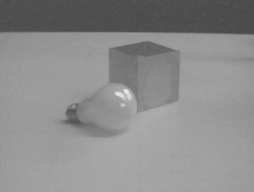
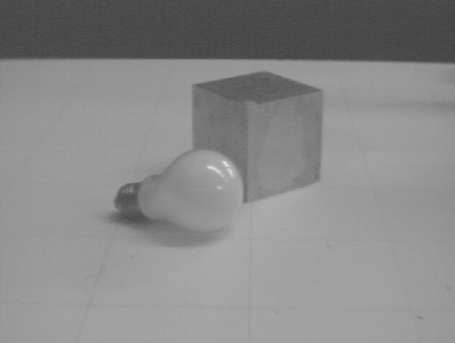
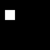
The image
shows the basic effects of graylevel dilation. This was produced from
by two erosion passes using a 3×3 flat square structuring element. The highlights on the bulb surface have increased in size and have also become squared off as an artifact of the structuring element shape. The dark body of the cube has shrunk in size since it is darker than its surroundings, while within the outlines of the cube itself, the darkest top surface has shrunk the most. Many of the surfaces have a more uniform intensity since dark spots have been filled in by the dilation. The effect of five passes of the same dilation operator on the original image is shown in
There are many specialist uses for dilation. For instance it can be used to fill in small spurious holes (`pepper noise') in images. The image
shows an image containing pepper noise, and
shows the result of dilating this image with a 3×3 square structuring element. Note that although the noise has been effectively removed, the image has been degraded significantly. Compare the result with that described under closing.
Dilation can also be used for edge detection by taking the dilation of an image and then subtracting away the original image, thus highlighting just those new pixels at the edges of objects that were added by the dilation. For example, starting with
again, we first dilate it using 3×3 square structuring element, and then subtract away the original image to leave just the edge of the object as shown in
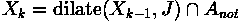
Finally, dilation is also used as the basis for many other mathematical morphology operators, often in combination with some logical operators. A simple example is region filling which is illustrated using
This image and all the following results were zoomed with a factor of 16 for a better display, i.e. each pixel during the processing corresponds to a 16×16 pixel square in the displayed images. Region filling applies logical NOT, logical AND and dilation iteratively. The process can be described by the following formula:
where  is the region which after convergence fills
the boundary, J is the structuring element and
is the region which after convergence fills
the boundary, J is the structuring element and
 is the negative of the boundary. This
combination of the dilation operator and a logical operator is also
known as conditional dilation.
is the negative of the boundary. This
combination of the dilation operator and a logical operator is also
known as conditional dilation.
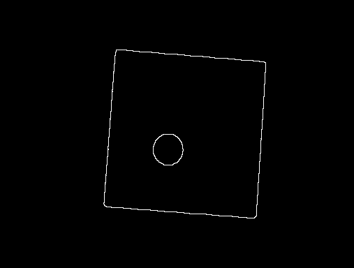
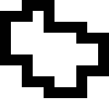
Imagine that we know  , i.e. one pixel which lies
inside the region shown in the above image, e.g.
, i.e. one pixel which lies
inside the region shown in the above image, e.g.
First, we dilate the image containing the single pixel using a structuring element as shown in Figure 1, resulting in
To prevent the growing region from crossing the boundary, we AND it with
which is the negative of the boundary. Dilating the resulting image,
yields
ANDing this image with the inverted boundary results in
Repeating these two steps until convergence, yields
and finally
ORing this image with the initial boundary yields the final result, as can be seen in
Many other morphological algorithms make use of dilation, and some of the most common ones are described here. An example in which dilation is used in combination with other morphological operators is the pre-processing for automated character recognition described in the thinning section.
You can interactively experiment with this operator by clicking here.
Figure 4 Cross-shaped structuring element
R. Gonzalez and R. Woods Digital Image Processing, Addison-Wesley Publishing Company, 1992, pp 518 - 519, 549.
R. Haralick and L. Shapiro Computer and Robot Vision, Vol. 1, Chap. 5, Addison-Wesley Publishing Company, 1992.
A. Jain Fundamentals of Digital Image Processing, Prentice-Hall, 1986, p 384.
D. Vernon Machine Vision, Prentice-Hall, 1991, pp 63 - 66, 76 - 78.
Specific information about this operator may be found here.
More general advice about the local HIPR installation is available in the Local Information introductory section.
©2003 R. Fisher, S. Perkins,
A. Walker and E. Wolfart.
![]()