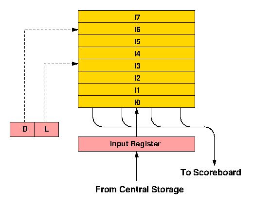
Figure 1 The CDC 6600 Instruction Stack
Figure 1 The CDC 6600 Instruction Stack
Instruction words are made up of four 15-bit parcels and as the first instruction word enters the bottom register of the stack (I0), the first two parcels within the word (starting from the left) are transferred into a series of instruction registers within the Scoreboard control logic (see under Parallel Functional Units). At the same time a further instruction fetch is initiated. Two parcels are taken to allow for long format (30-bit) instructions. If the first parcel is a short format (15-bit) instruction, the second parcel is ignored and in the next processor minor cycle the second and third parcels are taken from I0. When a long instruction is encountered an extra minor cycle is spent skipping over the second half, so that dealing with one complete instruction word never takes less than four 100 ns minor cycles. This matches the rate at which instructions move into the stack. Whenever a new instruction fetch is initiated, the contents of the stack ripple upwards one register every half minor cycle, with the topmost location (I7) being overwritten first. At the end of four minor cycles the contents of I0 are moved up and I0 is then ready to receive a new instruction from the Input Register.
In practice the rate at which instructions could be accessed from Central Storage turned out to be lower than anticipated at the design stage, which meant that a new instruction word would not actually be available until after a total of eight minor cycles. Since the rate at which instructions are issued to the functional units cannot often be maintained at one per minor cycle, however, the overall effect of this delay on performance is not quite so bad as might be imagined, and when executing loops which can be contained within the stack, no Central Storage accesses for instructions are required at all.
Information about the contents of the stack is contained in two registers: the Depth (D), which measures the number of valid instruction words in the stack, and the Locator (L), which specifies the location in the stack of the instruction word currently in use. During execution of a loop held entirely in the stack the instructions remain in fixed locations and the program address register can point to any one of the stack registers within a distance D from the bottom. D is re-set to zero whenever a branch out of the stack is taken, and is incremented by one for every new instruction word brought in. When the stack is full, D remains equal to seven.
When a conditional branch is decoded a test for jump within stack is made. This involves subtracting the current program address from the branch address. If the absolute value of the result is less than seven words, and if the values in D and L indicate that the branch is to a location within the stack, no further store accesses are made for instruction words until instruction parcels are again taken from I0. Thus a branch may jump forwards or backwards within the stack and loops may be held in the stack in various forms.
A very similar Instruction Stack was used in the STAR-100 computer, CDC's first commercially produced vector processor. The STAR-100 had a much longer instruction format than the 6600 so that its Instruction Stack was larger, being made up of sixteen 128-bit registers, but it used essentially the same control mechanisms. The main drawback of both the 6600 system and that used in the IBM System/360 Model 195 is that where the total number of instructions being obeyed in a loop will fit into the stack, but the code is actually made up of a number of non-contiguous segments (as in Figure 2, for example), the loop may not be caught in the stack. With machine code programming this situation can normally be avoided, but it is a common occurrence in compiler generated code and the increasing emphasis on high-level language programming has caused processor designers to seek alternative solutions. The CDC 7600 and Cyber 205, for example (successors, respectively, to the 6600 and STAR-100), both use associatively addressed buffers, with the 205 Instruction Stack again being correspondingly larger.
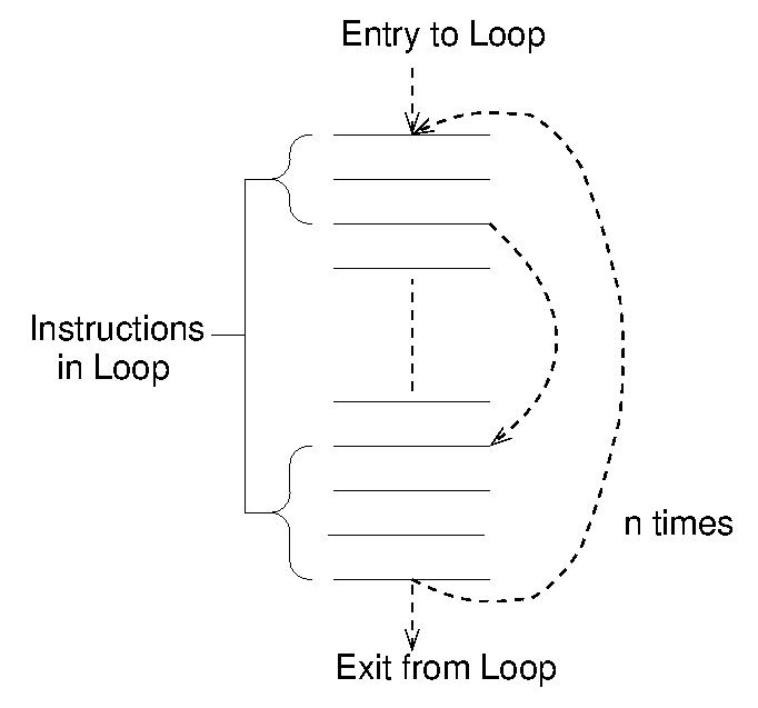
Figure 2 A Non-contiguous Instruction Loop