Each previously recognized subcomponent contributes a position estimate.
Suppose, the subcomponent has an estimated global reference frame
![]() and the transformation from the subcomponent to the main object is
and the transformation from the subcomponent to the main object is ![]() (given in the model).
(If the subcomponent is connected with degrees-of-freedom, then any variables
in
(given in the model).
(If the subcomponent is connected with degrees-of-freedom, then any variables
in ![]() will be bound before this step.
This is discussed here.)
Then, the estimated new global frame is
will be bound before this step.
This is discussed here.)
Then, the estimated new global frame is ![]() .
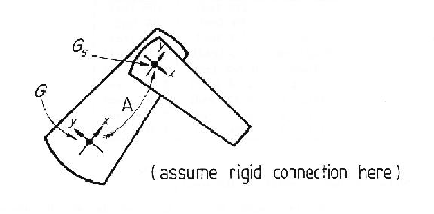
Figure 9.8 illustrates how the subcomponent's reference frame relates
to that of the object.
.
Figure 9.8 illustrates how the subcomponent's reference frame relates
to that of the object.
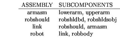
In the test image, these ASSEMBLYs had their positions
estimated by integrating estimates from subcomponents:
The reference frame estimates for these ASSEMBLYs are summarized in Tables
9.7 and 9.8.
Integrating the different position estimates sometimes gives better
results and sometimes worse
(e.g. robbodyside versus robot rotation).
Often, there was little effect (e.g. upperarm versus armasm rotation).
A key problem is that transforming the subcomponent's reference frame
expands the position estimates so much that it only weakly constrained the
ASSEMBLY's reference frame.
The numerical results for the whole robot in the test scene are summarized
in Table 9.9.
Here, the values are given in the global reference frame rather than in the
camera reference frame.
| PARAMETER | MEASURED | ESTIMATED |
|---|---|---|
| X | 488 (cm) | 486 (cm) |
| Y | 89 (cm) | 85 (cm) |
| Z | 554 (cm) | 554 (cm) |
| Rotation | 0.0 (rad) | 0.07 (rad) |
| Slant | 0.793 (rad) | 0.46 (rad) |
| Tilt | 3.14 (rad) | 3.53 (rad) |
| Joint 1 | 2.24 (rad) | 2.18 (rad) |
| Joint 2 | 2.82 (rad) | 2.79 (rad) |
| Joint 3 | 4.94 (rad) | 4.56 (rad) |
Better results could probably have been obtained using another geometric estimate integration method (e.g. [63,57]). However, the results here are generally accurate, mainly because of the richness of information in the surface image and geometric object models.