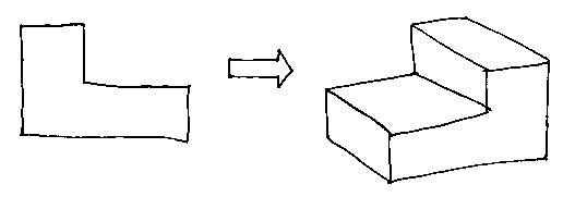
Suppose a solid with flat faces and no holes has F faces, E edges, and V vertices.
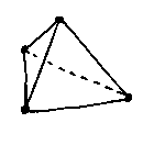
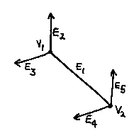
A tetrahedron is the simplest:
In this case F + V - E = 2. This is also true for a cuboid (try it). Is it true in general?
F = 4
E = 6
V = 4
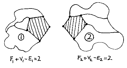
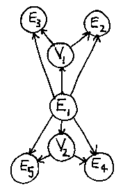
Suppose we have two solids, 1 and 2, and we know that the formula is true for each of them because we've counted. Suppose also that the solids each have a face which is the mirror image of the corresponding face on the other (the shaded pentagons). These faces don't have to be pentagons; say in general that they each have n edges.
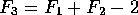
What happens if we glue the solids together at the shaded faces to make a more complicated object, called 3?
The two faces disappear, so we know that:
Two sets of n vertices become one, so we know that:
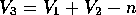
Two sets of n edges become one, so we know that:
So

Which we can rearrange:

But we know that the first two parts in brackets both equal 2. The n terms cancel, leaving us with:
So the formula F + V - E = 2 works for all solids without holes, because we can start with simple solids (like the tetrahedron) for which we know the formula is true, and build complicated solids by gluing faces together.
Q.E.D.
This is known as the Euler-Poincaré formula, after its discoverers.
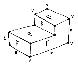
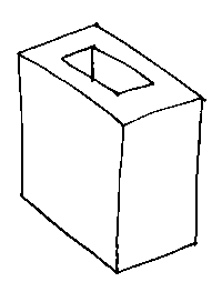
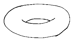
What about solids with holes? Most real engineering components have holes, so we have to be able to deal with them. Think about gluing together two objects such that they will make an object with a hole:
The argument in the proof above about edges and vertices stays the same, but now

Where there are H holes. This gives us:

Check for this object:
So it works for that.
F = 16
E = 32
V = 16
H = 1
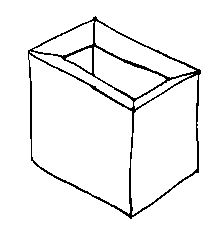
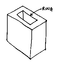
What about this one?
WRONG!
F = 10
E = 24
V = 16
H = 1
The problem is caused by the flat faces with rings of edges and vertices `floating' in them unconnected by edges to the other vertices.
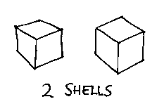
If we fix that up (say there are R rings), and also allow for the fact that we may want to describe two or more completely separate objects (called shells; suppose there are S of them), we come to the final version of the Euler-Poincaré formula:

The number of holes through an object, H, is called the genus of the object.
An object for which the formula is true is guaranteed to be a genuine solid (or collection of solids) as far as its topology is concerned. Topology is the study of shapes without any information about the coordinates of things (that is, without any geometry). All the proofs above were done without any reference to the actual positions of the edges and vertices and so on - they were topological proofs.
And as we shall see, there may still be geometrical problems...
But first:
How are boundary-representation models represented in the computer?
This is a picture of a single edge, ending in two vertices, which then each have two other edges leading off from them. The edge might, for example, be an edge of a cuboid.
This is how the edge might be represented in the computer. The edge has pointers to the vertices at its ends, and to the next edges. A pointer is essentially the address in the computer's memory where something is stored. The vertices have pointers to their (x, y, z) coordinates, and so on. This structure is called Baugmart's winged edge data structure after its inventor. The `winged edge' phrase refers to the edge and its adjoining faces, which look (a bit) like a dihedral wing.
How can we build and modify this structure?
Many (though not all) boundary-representation modellers have procedures (or SUBROUTINES in F*RTR*N-speak) called Euler-operators. These modify the face-edge-vertex pointer structure in such a way that the Euler-Poincaré formula is always kept true.
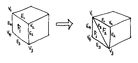
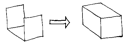
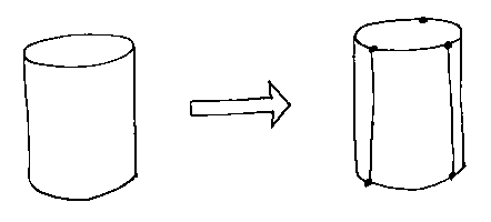
Here is an example: make_edge_and_face(f1, v1, v3).
This would take the cuboid on the left, and split the face in two along its diagonal, making a new object. Note that in the original cuboid, v1...v4 must all lie in a plane, but in the new object v2 is free to move along the top-right edge.
Here is another example: kill_shell_make_rings(....)
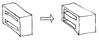
And another: kill_ring_make_edge(....)
Note that, as an object is being constructed, it may temporarily be in a non-solid state. Some systems (for example ACIS) allow their users access to such non-solid models, but keep everything organized so that you can always build real solids if you know you need to. Some systems force their users only to deal with solids, and keep all the messy hanging faces and the like strictly to their internals. This leads us to:
An important distinction
Objects with hanging zero-thickness faces, edges sticking out like whiskers and so on are called non-manifold objects. Modellers that can deal properly with these, and that can ensure solidity when you need it, are called geometric modellers because they are modelling all (well, nearly all...) geometry. Modellers that restrict their attention to solids alone are called solid modellers.
Generally speaking geometric modellers are more advanced programs than solid modellers.
What problems remain?
Two main ones:
What does item 2 mean?
1. We still don't have solids with curved surfaces, and
2. The Euler-Poincaré formula ensured topological solidity, but didn't say anything about the geometry.
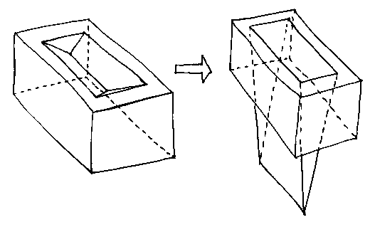
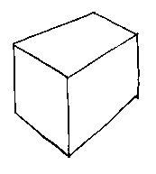
Suppose we make the house-brick on the left. The Euler-Poincaré formula will rightly tell us that it's a solid.
But now suppose that we reduce the z coordinates of the two vertices at the bottom of the frog without changing anything else.
For a few centimeters everything is fine. The brick stays solid. But when the bottom of the trough passes through the bottom face of the brick we're left with a nonsense object.
So. Face-edge-vertex topology is not enough to ensure solidity.
In addition, the system has to check that, when something moves, it does not cut through anything else. If such a cut is found, the appropriate Euler operators must be called to patch up the data structure and force things to stay solid.
This is fine, but we can still have problems because the computer can only use approximations to coordinates (about 6 decimal places, or 12 if you're prepared to double the memory you're spending). So near-misses can confuse the system as to whether the data structure should be changed or not. For example, the bottom of the brick frog may be very close to the bottom face of the brick.
How do we get shapes into a boundary-representation modeller?
If we had to use the Euler operators directly, that would be very inconvenient. There are two main ways of getting shapes into b-rep modellers.
The first is to use a set-theoretic modeller, which you will encounter later in the course.
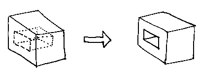
The second is to start with a lamina two-dimensional shape and to extrude it to make a solid. The system patches up the winged edge data structure as it does the extrusion.
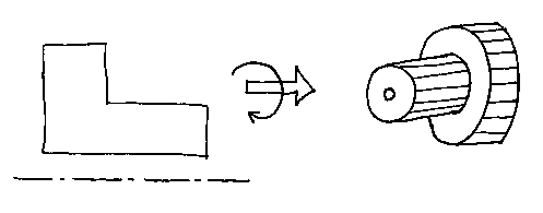
It is also possible to turn a lamina into a solid of revolution in a similar way. (In the picture the solid is a faceted approximation, because we haven't done curved surfaces yet.)
In general, shapes made this way are called sweeps.
Curved surfaces in boundary-representation modellers
Clearly, for serious engineering use, any geometric modeller must be able to represent objects with curved surfaces as well as the flat facets that we've already encountered.
Most modellers allow the following shapes:
Flat planes - we've already seen these. The algebraic expression for a plane is of degree 1 (degree is the highest power of x, y, or z).
Cylinders - rare is the piece of engineering that doesn't have at least one. Cylinders are degree 2.
Spheres - less common than cylinders, but still pretty essential. Spheres are degree 2.
Cones - about as common as spheres. Cones are also degree 2.
The torus - this seems rather exotic. Why include it? For an answer, think about the shape of a fillet where a cylindrical pipe meets a flat surface at right angles. Tori are degree 4.
In addition to these, many geometric modellers allow more complicated curved shapes called sculptured surfaces, which we will deal with in a later lecture.
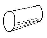
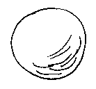
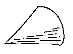
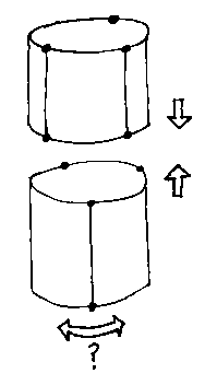
What problems will we encounter in trying to include these solids in a boundary-representation modeller? For example, a cylinder is a single shell with no rings or holes. How does it measure up against the simple Euler-Poincaré formula F + V - E = 2?
WRONG!
F = 3
E = 2
V = 0
A solution to this which is commonly adopted is to pretend that the cylinder is a triangular prism (or other regular polygonal prism) with arcs as edges rather than straight lines. We know that the Euler-Poincaré formula works for such prisms, so sanity is restored.
Some of the component primitives of the cylinder (its edges and faces) will, in a practiacal boundary-representation modeller, have a flag attached to their data structure to say that the object of which they are a part is really a cylinder, not a prism. We'll return to this in a moment.
Problems still remain, unfortunately:
How does the system join two cylinders when their `vertices' don't line up? One could be rotated, but it probably isn't isolated; if it's connected to other bits that can't be rotated, the modeller may have to insert extra redundant information to keep its data structures clean.
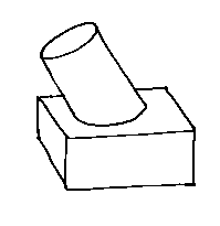
Another problem is that the boundary-representation modeller has to be able to compute (or at least approximate) curves of intersection between all the shapes that it can represent. A cylinder and a plane give an ellipse, which isn't too bad. But...
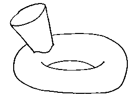
...a cone and a torus give a horrible curve which may also fall into several different pieces.
In general, if we have N different shapes to start with, there will be

possible different types of curves of intersection.
Another problem:
When the modeller renders a picture of a curved object, the horizon lines (dotted) aren't actually lines in the model; they have to be added to the picture to make it realistic. The usual solution to this is to facet the model then plot the facets, which makes the problem go away.
All these difficulties are a pain, but they have all been solved. Boundary-representation modellers are a bit like motor cars: a great deal of technical development has gone into them over the years, making them very successful. But if you were starting from scratch, you probably wouldn't go down that road...
Strengths and weaknesses of b-rep geometric modellers
[A primitive is one of the building blocks of a model, such as an edge. Local means you know where the primitives are in space, and they are finite in extent.]Making pictures is easy
Calculating volume (hence mass) is hard
Diversion: The depth buffer method of rendering.
© Adrian Bowyer 1996