The goal of cylindrical pixel transfer is an automatic and reliable estimate of pixel correspondences between reference-views and visual prediction. The available knowledge consists of camera focal length in pixels, landmark position, orientation and reference-views, and an estimate of current robot pose. In addition, there is the knowledge that learned landmarks lie on planar or "almost planar" surfaces.
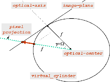
The basic concept for interpolating cylindrical panoramic images has been shown in figure 1. This is equivalent to computing 3D points from image correspondences and projecting them to a new target image. McMillan and Bishop, [19], devised an efficient method for transferring known image disparity values between cylindrical panoramic images to a new virtual view. Their approach uses the angular disparity (related to each cylindrical pair) to automatically generate warps that map reference views to arbitrary cylindrical or planar views.
The angular disparity can be estimated in different ways depending on the available knowledge. For example, by manually or automatically specifying a sparse set of corresponding points that are visible in both reference-views, by knowing or recovering camera internal parameters, and by exploiting epipolar geometry, a dense set of corresponding points can be recovered. Examples of procedures which exploit epipolar relations to recover dense correspondences from a sparse set of corresponding points, can be found in different literature works, (McMillan and Bishop [19], Faugeras [9], Blanc, Livatino and Mohr [3], [2]).
In the case of [14], the angular disparity is inferred from previously estimated correspondences along cylindrical epipolar lines. These correspondences allowed for estimating the geometry of the landmark surface based on: 3D positions of landmark center, a minimum of two landmark corners, and the result of the planarity test, Landmarks are required to lie on one planar or "almost planar" surface, nevertheless, the same procedure could be applied to landmarks lying on more than one surface (in case the surfaces are known).
The proposed rendering system takes as input cylindrical reference-views of landmarks, along with the map of the angular disparities. This information is used to automatically generate image warps that map landmark reference-views to arbitrary cylindrical landmark-views. Note that the generated warps are capable of describing perspective effects, and occlusions (using a simple visibility algorithm that guarantee back-to-front ordering [19]).
|
The cylindrical-to-cylindrical mapping is illustrated in figure
2.
Each angular disparity value,
![]() , can be obtained as
in equation 1.
Note that
, can be obtained as
in equation 1.
Note that
![]() are the pixel coordinates in the panorama, where
are the pixel coordinates in the panorama, where
![]() is an angle while
is an angle while ![]() is the pixel row.
is the pixel row.
where
![]() represents a generic pixel in
one of the left cylindrical reference-views (labeled "left") identified
by the angle
represents a generic pixel in
one of the left cylindrical reference-views (labeled "left") identified
by the angle ![]() and the ordinate
and the ordinate ![]() , and
, and
![]() represents the correspondent
ordinate
represents the correspondent
ordinate ![]() for a certain angle
for a certain angle ![]() , in the right reference-view.
, in the right reference-view.
Knowing the angular disparity for each landmark pixel, this can be converted
for each position on the left cylinder (![]() ,
, ![]() ),
into an image flow vector field, (
),
into an image flow vector field, (
![]() ,
,
![]() ).
The figure 2 top row illustrates this conversion.
).
The figure 2 top row illustrates this conversion.
The disparity values can then be transfered from the known cylindrical
pairs
![]() and
and
![]() (which respectively represent the left and the
right camera positions), to a new cylindrical projection in an
arbitrary position,
(which respectively represent the left and the
right camera positions), to a new cylindrical projection in an
arbitrary position,
![]() , using
the following equations, where
, using
the following equations, where ![]() is the rotation offset which
aligns the angular orientation of the cylinders to a common frame,
is the rotation offset which
aligns the angular orientation of the cylinders to a common frame,
 |
(2) |
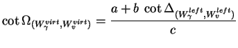
The resulting
![]() is the
angular disparity between the generic pixel in the left cylindrical
reference-view,
is the
angular disparity between the generic pixel in the left cylindrical
reference-view,
![]() , and the corresponding pixel in
the virtual cylindrical view.
In this way, each resulting angular disparity value,
, and the corresponding pixel in
the virtual cylindrical view.
In this way, each resulting angular disparity value,
![]() , can be converted, for each position on the left
cylinder (
, can be converted, for each position on the left
cylinder (![]() ,
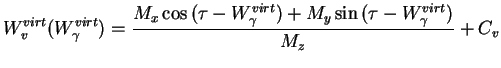
, ![]() ), into an image flow vector field (
), into an image flow vector field (
![]() ,
,
![]() ) using the
epipolar relation given by equation 4.
) using the
epipolar relation given by equation 4.
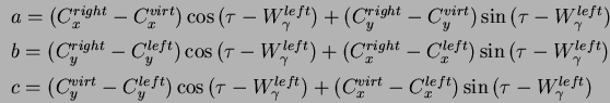
where
![\begin{displaymath}\left[
\begin{array}{c}
M_x \\
M_y \\
M_z
\end{array}\right...
...- W^{left}_{\gamma})} \\
C_v - W^{left}_{v}
\end{array}\right]\end{displaymath}](img27.png) |
(5) |
and
| (6) |
where ![]() is the rotation offset which aligns the angular orientation of
the cylinders to a common frame, and
is the rotation offset which aligns the angular orientation of
the cylinders to a common frame, and ![]() is ordinate
is ordinate ![]() of the
scan-line where the center of the projection would project onto the
scene, (i.e. the ordinate of the line of zero elevation).
of the
scan-line where the center of the projection would project onto the
scene, (i.e. the ordinate of the line of zero elevation).
The above equation gives a concise expression for the curve,
![]() , (i.e. the cylindrical epipolar
line), formed by the projection of a ray across the surface of a
cylinder, (labeled "virt"), where the ray is specified by its
positions on some other cylinder, (labeled "left").
, (i.e. the cylindrical epipolar
line), formed by the projection of a ray across the surface of a
cylinder, (labeled "virt"), where the ray is specified by its
positions on some other cylinder, (labeled "left").
Once the angular disparity,
![]() , has been used for
the transfer of the disparity values between the reference cylinder to
a new viewing position, each estimated pixel in the virtual cylinder,
, has been used for
the transfer of the disparity values between the reference cylinder to
a new viewing position, each estimated pixel in the virtual cylinder,
![]() , is projected on the virtual camera image-plane, so becoming
, is projected on the virtual camera image-plane, so becoming
![]() , in order to generate the landmark visual prediction.
The visual prediction is converted to planar to be compared to
landmark current observation.
Figure 3 illustrates the mapping from cylindrical to
planar image.
, in order to generate the landmark visual prediction.
The visual prediction is converted to planar to be compared to
landmark current observation.
Figure 3 illustrates the mapping from cylindrical to
planar image.
The proposed landmark pixel transfer procedure starts with a forward mapping (from reference to virtual) for what concern the landmark corners (which position has been previously established by stereo-matching). This results in a region of the virtual-cylinder delimited by the four projected corners. Each pixel included in the delimited region is then projected forward or inverse depending on the required performance. Having in this case priority a high texture fidelity, a forward mapping is adopted in the compression case and an inverse mapping in the enlargement case.
In summary, the proposed technique of cylindrical pixel transfer allows for establishing pixel correspondence between landmark reference-views and virtual prediction. In particular, two reference views were considered. Experiments, (Livatino [14]), showed that the proposed technique allows for reliable matches between prediction and observation even in presence of significant positional errors, (denoted by clear displacements in image-plane, between prediction and observation).