The elongation of a surface region is also a distinguishing characteristic. This has been a traditional pattern recognition measurement applied to two dimensional regions, but a three dimensional version can also be obtained.
For a planar surface, elongation is the ratio of the longest to the shortest dimension of a planar rectangular box circumscribing the surface, which is similar to the two dimensional definition. The definition can be adapted to curved surfaces by using the maximum and minimum arc lengths of the intersection of the surface and a plane normal to the surface. The arc length should be calculated for all intersections of the surface, but this is time-consuming. Instead, only the cross-section widths about a central point are used.
The four factors involved in the estimation of the surface's dimensions are: the image region's dimensions, the surface slant relative to the viewer, the curvature of the surface, and the distance from the viewer. It is possible to approximate the elongation after separating the effects of these factors.
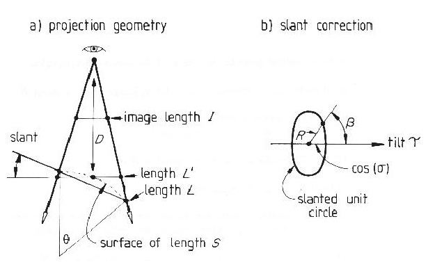
Figure 6.12 part (a) shows a sketch of the viewing
relationship at one cross-section through the surface.
By the discussion in the previous section, the cross-section length ![]() is
approximately related to the chord length
is
approximately related to the chord length ![]() as:
as:
This analysis is then modified for observed slant
compression at angles other than the tilt angle.
Figure 6.12 part (b) shows the geometry used for the following analysis.
This figure shows a unit circle compressed by a slant angle ![]() in the direction
in the direction ![]() and orthographically projected onto the image plane.
Elementary trigonometry and algebra show that the observed length
and orthographically projected onto the image plane.
Elementary trigonometry and algebra show that the observed length ![]() at the
angle
at the
angle ![]() is:
is:
The computation of the elongation value is then:
| Let: | |
|
|
|
| the cross-section at image angle |
|
Then, the tilt angle is:
The elongations for all unobscured image
regions that directly correspond to model SURFACEs are listed in Table 6.9.
These results show that the estimation process gives approximate results when applied to unobscured regions. In part, small regions should be more affected because single pixel errors are significant, but this is not always the case.
A weakness of the process is that it only estimates the dimensions based on reconstructions about a single point, which produces lower bounds for the maximum and upper bounds for the minimum cross-sections. This should result in an estimate that is lower than the true elongation. However, the key source of error is the small size of the regions coupled with image quantization. Other sources of error are the hand measured surface data, surface interpolation and the curvature correction process assuming uniform curvature along the cross-section path. However, the approximations were felt to be justifiable on practical grounds and the above results show that the approach is acceptable.