A SURFACE's spatial position is represented by the transformation from the camera coordinate frame to that of the SURFACE. Several constraints are available to help deduce the transformation.
Fisher [66] showed how the transformation could be deduced using the two dimensional boundary shape. Estimation of the orientation parameters (rotation, slant and tilt) used the cross-section width as a function of the image angle, which deforms in a characterizable way.
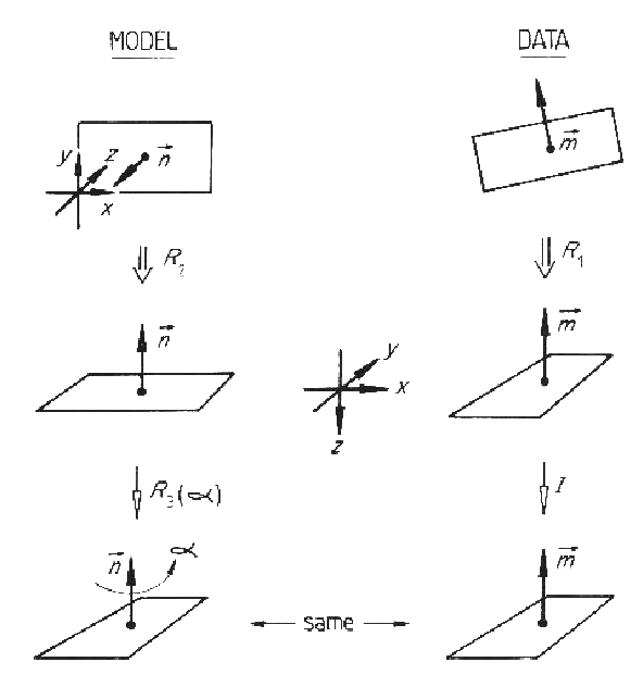
In the research presented here, surface normals are directly available. If a planar data patch is paired with a model patch, their normal vectors must be parallel so only one rotational degree-of-freedom needs to be resolved. The final rotation degree-of-freedom is estimated by correlating the angular cross-section width as a function of rotation angle. Figure 9.2 illustrates this. For non-planar surfaces, an approximate solution is obtained by using the normals at the centroids of the surfaces. A more complete solution using the curvature axis is presented below.
The complete method is:
| Rotate the image surface until the central point normal is aligned with the -Z camera axis ( |
|
| Rotate the model SURFACE until the central point normal is aligned with the -Z camera axis ( |
|
| Calculate data surface cross-section widths. | |
| Calculate model SURFACE cross-section widths. | |
| For each rotation angle ( |
|
| calculate model rotation ( |
|
| correlate cross-section widths | |
| Set a threshold = 0.9 * peak correlation. | |
| Pick peak correlations ( |
|
| (If more than 30% above threshold, declare circularly symmetric: |
|
| Solve for reference frames:
|
|
Some of the estimated and nominal rotation values for the modeled SURFACEs successfully invoked in the test image are given in Table 9.1. The full set of results are in [67], and those shown here include the best, worst and typical results. All values given in the tables below are in the camera reference frame. The estimates shown here are only the mean values of the estimate intervals, whose size depends on the input data error and the amount of parameter space intersection.
The rotation estimates are good, even on small SURFACEs
(robshoulds) or partially obscured SURFACEs (uside, uends, lsideb, ledgea).
| Image | Measured (rad) | Estimated (rad) | ||||||
|---|---|---|---|---|---|---|---|---|
| SURFACE | Region | ROT | SLANT | TILT | ROT | SLANT | TILT | |
| robbodyside | 8 | 0.00 | 0.13 | 4.71 | 0.02 | 0.13 | 4.76 | |
| robshoulds | 29 | 0.05 | 0.70 | 6.08 | 0.02 | 0.84 | 6.15 | |
| uside | 19,22 | 6.04 | 0.88 | 3.48 | 5.20 | 0.88 | 4.32 | |
| uends | 25 | 3.12 | 0.75 | 2.75 | 3.16 | 0.66 | 3.21 | |
| lsideb | 12 | 1.51 | 0.88 | 1.73 | 1.70 | 0.88 | 1.54 | |
| tcanoutf | 9 | 0.00 | 0.13 | 4.71 | 0.02 | 0.11 | 4.56 | |
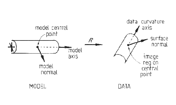
SURFACE orientation can be estimated without using the boundary if there is significant surface curvature in one direction. Here, the three dimensional orientation of the major curvature axis constrains the remaining angular degree-of-freedom to two possible orientations. The transformation from the model normal and curvature axis vectors to those of the data gives the orientation estimate. Data errors complicate the calculation, which is described in detail here. Figure 9.3 illustrates the process of rotation estimation using the normal and curvature axis. Table 9.2 lists the results for this case.
| Image | Measured (rad) | Estimated (rad) | ||||||
|---|---|---|---|---|---|---|---|---|
| SURFACE | Region | ROT | SLANT | TILT | ROT | SLANT | TILT | |
| robbodyside | 8 | 0.00 | 0.13 | 4.71 | 6.28 | 0.13 | 4.77 | |
| robshoulds | 29 | 0.05 | 0.70 | 6.08 | 0.10 | 0.83 | 6.07 | |
| uends | 25 | 3.12 | 0.75 | 2.75 | 3.12 | 0.66 | 3.24 | |
| tcanoutf | 9 | 0.00 | 0.13 | 4.71 | 0.01 | 0.18 | 4.61 | |
Table 9.3 shows the results obtained by integrating the above
results with those from Table 9.1 (by parameter space
intersection).
As the curvature based estimation process gives nearly the same results
as the boundary based process, the intersection hardly improves the results.
This suggests that the initial estimation techniques are both generally
accurate.
| Image | Measured (rad) | Estimated (rad) | ||||||
|---|---|---|---|---|---|---|---|---|
| SURFACE | Region | ROT | SLANT | TILT | ROT | SLANT | TILT | |
| robbodyside | 8 | 0.00 | 0.13 | 4.71 | 0.01 | 0.13 | 4.76 | |
| robshoulds | 29 | 0.05 | 0.70 | 6.08 | 0.02 | 0.83 | 6.15 | |
| uends | 25 | 3.12 | 0.75 | 2.75 | 3.16 | 0.66 | 3.21 | |
| tcanoutf | 9 | 0.00 | 0.13 | 4.71 | 0.01 | 0.18 | 4.56 | |