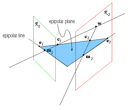
Let us consider a stereo rig composed by two pinhole cameras
(Fig. 2). Let ![]() and
and ![]() be the optical
centres of the two cameras. A 3D point
be the optical
centres of the two cameras. A 3D point ![]() is projected onto
both image planes, to points
is projected onto
both image planes, to points ![]() and
and ![]() , which
constitute a conjugate pair. Given a point
, which
constitute a conjugate pair. Given a point ![]() in the left
image plane, its conjugate point in the right image is constrained to
lie on a line called the epipolar line (of
in the left
image plane, its conjugate point in the right image is constrained to
lie on a line called the epipolar line (of ![]() ). This line is
the projection through
). This line is
the projection through ![]() of the optical ray of
of the optical ray of ![]() ;
indeed
;
indeed ![]() may be the projection of an arbitrary point on its
optical ray.
may be the projection of an arbitrary point on its
optical ray.
|
Furthermore one should observe that all the epipolar lines in one image plane pass through a common point called the epipole, which is the projection of the conjugate optical centre:
![]()
The parametric equation of the epipolar line of
![]() writes:
writes:
![]()
In image coordinates it becomes:
where ![]() and
and
![]() is the projection operator extracting the ith component from a
vector.
is the projection operator extracting the ith component from a
vector.
 |
 |
 |
 |
When ![]() is in the focal plane of the right camera, the right
epipole is at infinity, and the epipolar lines form a bundle of
parallel lines in the right image. Analytically, the direction of each
epipolar line can be obtained by taking the derivative of the
parametric equations (13,14) with respect to
is in the focal plane of the right camera, the right
epipole is at infinity, and the epipolar lines form a bundle of
parallel lines in the right image. Analytically, the direction of each
epipolar line can be obtained by taking the derivative of the
parametric equations (13,14) with respect to
![]() :
:

Note that the denominator is the same in both components, hence it
does not affect the direction of the vector. The epipole is rejected
to infinity when ![]() . In this case, the direction
of the epipolar lines in the right image doesn't depend on
. In this case, the direction
of the epipolar lines in the right image doesn't depend on ![]() any more and all the epipolar lines becomes parallel to vector
any more and all the epipolar lines becomes parallel to vector
![]() .
.
A very special case is when both epipoles are at infinity, that
happens when the line containing ![]() and
and ![]() (the
baseline) is contained in both focal planes, or the retinal planes
are parallel to the baseline. Epipolar lines form a bundle of parallel
lines in both images.
(the
baseline) is contained in both focal planes, or the retinal planes
are parallel to the baseline. Epipolar lines form a bundle of parallel
lines in both images.
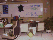
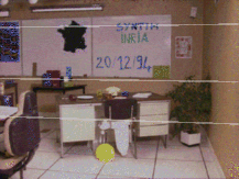
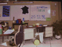
Any pair of images can be transformed so that epipolar lines are parallel and horizontal in each image as in Fig. 3. This procedure is called rectification.